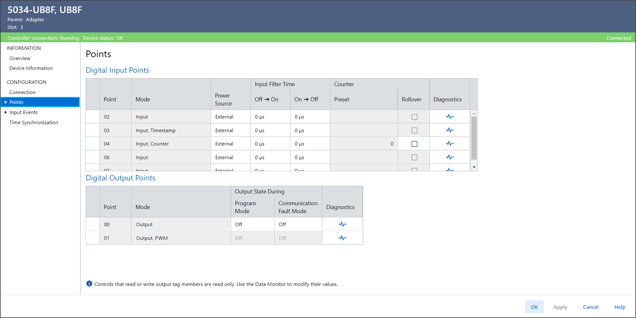
Points View
Use Points to view or configure the points for the device.
Points View Example
The Points view includes these parameters for Disabled Points:
Parameter | Description |
|---|---|
Disabled Points | Displays the points that have been disabled. |
The Points view includes these parameters for Digital Input Points:
Parameter | Description |
|---|---|
Point | Displays the point number to which this configuration
applies. |
Mode | Displays the mode for the point. |
Power Source | Defines the power source for the point.
|
Input Filter Time Off → On | Defines how long an Off to On input transition must remain in the
On state before the device considers the transition valid. |
Input Filter Time On → Off | Defines how long an On to Off input transition must remain in the
Off state before the device considers the transition valid. |
Preset | Displays the value, set in the output tag Preset, to use for
counter preset. The value can range from 0…2,147,483,647. |
Rollover at Preset | Determines the action that is taken when the input tag Count
reaches the output tag Preset value.
|
Diagnostics | Opens the Diagnostics dialog, which contains diagnostic
information. |
The Points view includes these parameters for Digital Output Points:
Parameter | Description |
|---|---|
Point | Displays the point number to which this configuration
applies. |
Mode | Displays the mode for the point. |
Output State During Program Mode | Determines the behavior of each output when the controller
transitions to Program Mode or Inhibit mode. While in Program
Mode or Inhibit mode, outputs from the controller are ignored
and the output behaves as follows:
|
Output State During Communication Fault Mode | Determines what happens to the output of each point after a
communication fault occurs and the module enters Communication
Fault Mode.
|
Diagnostics | Opens the Diagnostics dialog, which contains diagnostic
information. |
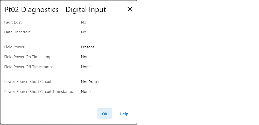
Ptxx Diagnostics
To view the Ptxx diagnostics, select Diagnostics in the Points or Ptxx view.
Ptxx Diagnostics Example
Provide Feedback