Ptxx – Digital Input, Counter View
Use Ptxx – Digital Input, Counter to view or configure the points for the device.
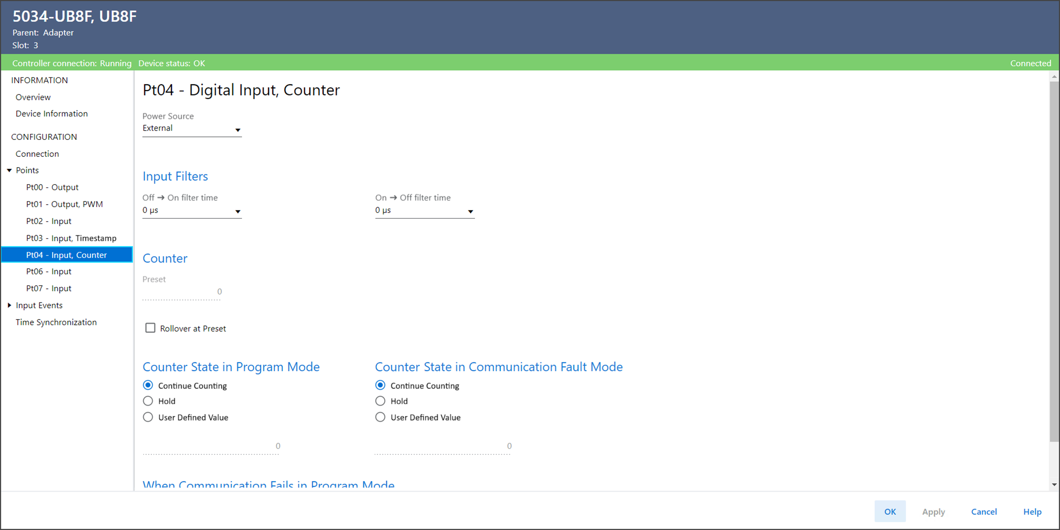
Ptxx – Digital Input, Counter View Example
The Ptxx – Digital Input, Counter view includes these parameters:
Parameter | Description |
|---|---|
Power Source | Defines the power source for the point.
|
Input Filters Off → On Filter Time | Defines how long an Off to On input transition must remain in the
On state before the device considers the transition valid. |
Input Filters On → Off Filter Time | Defines how long an On to Off input transition must remain in the
Off state before the device considers the transition valid. |
Preset | Displays the value, set in the output tag Preset, to use for
counter preset. The value can range from 0…2,147,483,647. |
Rollover at Preset | Determines the action that is taken when the input tag Count
reaches the output tag Preset value.
|
Counter State in Program Mode | Determines the behavior of each counter when the controller
transitions to Program Mode or Inhibit mode. While in Program
Mode or Inhibit mode, the counter behaves as follows:
|
Counter State in Program Mode User-defined Value | Defines the value that is set to count when Counter State in
Program Mode is selected as User-defined value. |
Counter State in Communication Fault Mode | Determines what happens to the counter after a communication
fault occurs and the module enters Communication Fault Mode.
|
Counter State in Communication Fault Mode User-defined Value | Defines the value that is set to count when Counter State in
Communication Fault Mode is selected as User-defined value. |
Counter State When Communication Fails in Program Mode | Determines the counter action if communication fails in Program
Mode.
|
Diagnostics | Opens the Diagnostics dialog, which contains diagnostic
information. |
Provide Feedback