Add the Adapter to a Project
- Verify that your project is online.
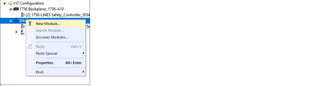
- Right-click on your network port, and select New Module.
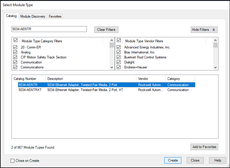
- On the Select Module Type dialog, complete the following tasks:
- In the search field, type the catalog number for your adapter.This example uses the 5034-AENTR adapter.
- Select your adapter from the search result.For some modules, the Select Major Revision dialog can appear. If this dialog appears, choose the major revision of the module and select OK
- Select Create.
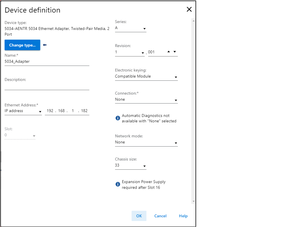
- From the Device definition dialog, complete the following:
- Enter a name for your adapter.
- Enter the IP address in the Ethernet Address field.
- Set appropriate firmware revision of your adapter. Use the left and right dropdowns under the Revision.OptionDescriptionMajor revision (left dropdown menu)This field only displays the major revisions that are applicable to the selected series. This field appears dimmed when online unless the module supports allowing major revision changes to be made while online.Minor revision (right field)Sets the minor revision of the module. The valid range is 1…255. This field is enabled while offline, and in the Program, Remote Program, and Remote Run modes. It appears dimmed in Run mode or when the Electronic Keying is set to Disable Keying.
- Select the appropriate the Electronic Keying setting.AttributeDescriptionVendorThe device manufacturerDevice TypeThe general type of the product, for example, digital I/O module.Product CodeThe specific type of the product. The Product Code maps to a catalog number.Major RevisionA number that represents the functional capabilities of a device.Minor RevisionA number that represents behavior changes in the device.
- Select the connection type from the Connection type dropdown list.Connection OptionsDescriptionNoneNo direct connection from the controller (Originator) to the adapter.StatusReports the device status.
- Select the network mode from the Network mode dropdown list.Network Mode OptionsDescriptionDevice Level Ring (DLR)Provides redundant paths.Parallel Redundancy Protocol (PRP)Duplicated data at the physical level for each path.
- Set the Chassis size to the number of modules including the adapter. For example, one adapter with 32 I/O modules is considered as Chassis size 33.
- Select OK. If you set the Connection to Status, select Yes on the Apply changes dialog.
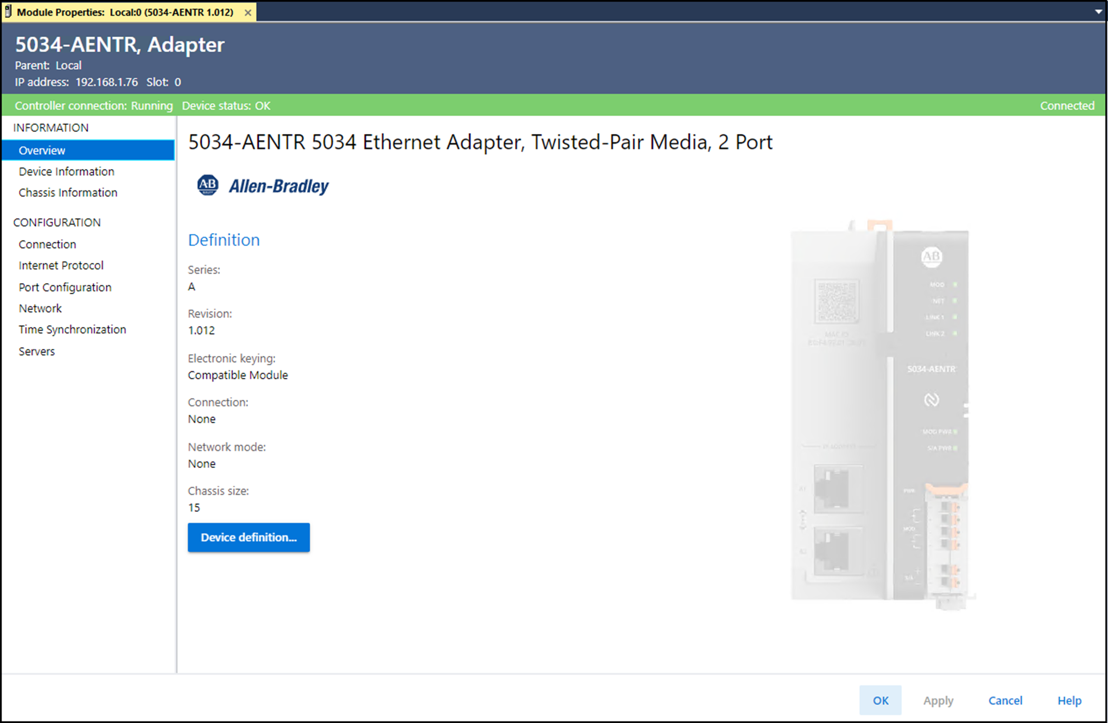
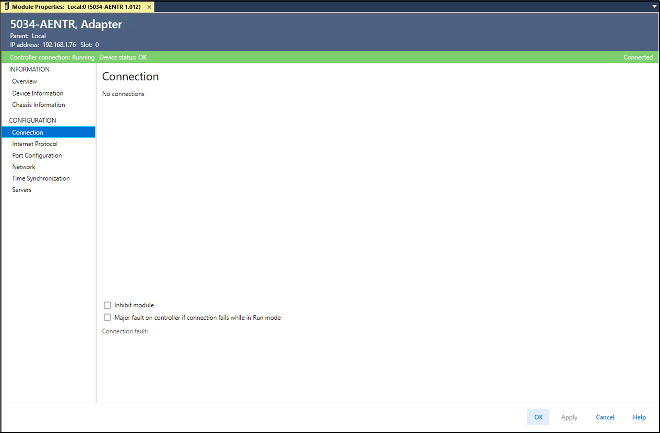
- On the New Module dialog, select the Connection from Configuration and complete the following tasks:
- Set the Requested Packet Interval (RPI). The acceptable range is 25.0…750.0 ms, with 200.0 ms as the default. This connection is for status data only, with no I/O.
- Set the Connection over EtherNet/IP to Unicast or Multicast from the dropdown list.For non-redundant controllers, the default value is Unicast when the target device supports unicast. Otherwise, the default value is Multicast. For redundant controllers, the default value is Multicast when the target device supports multicast. Otherwise, the default value is Unicast.
- Select OK.
- Save the project.
- If the project does not have a communication path to the controller, select Browse to create a path.
- On the Who Active dialog, choose the desired path and select Set Project Path and close the dialog.
- Verify that the controller mode switch is in the PROG mode position.
- Right-click on the Controller Status icon, and select Go Online.
- On the Connected To Go Online dialog, select Download.
- Confirm that you want to download the project.The project downloads to the controller. The Connected To Go Online dialog closes when the download is complete.
Provide Feedback