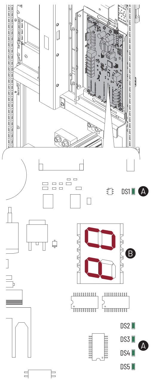
AC Precharge Circuit Board Status Indicators
The
PowerFlex®
755T AC precharge module uses status indicators and a 7-segment display to report conditions.AC Precharge Status Indicators
Item | Description |
|---|---|
A | DS1…DS5 status indicators. |
B | 7-segment display. |
Color | State | Description |
|---|---|---|
Green | Flashing | Fiber connection is online. |
Red | Flashing | Fiber connection is offline. |
Color | State | Description |
|---|---|---|
Green | Steady | 240V AC Okay |
Yellow | Steady | 240V AC Low Alarm |
Red | Flashing | 240V AC Loss Fault |
Unlit | Off | 240V AC Loss Alarm |
Color | State | Description |
|---|---|---|
Green | Steady | Fiber connection is online. |
Yellow | Flashing | Communications Loss |
Unlit | Off | Inactive |
Color | State | Description |
|---|---|---|
Green | Steady | Precharge Done (Main circuit breaker is closed.) |
Green | Flashing | Main circuit breaker is closing. |
Yellow | Steady | Main circuit breaker is opening. |
Yellow | Flashing | Not Ready |
Red | Flashing | Main circuit breaker opened. |
Unlit | Off | Ready |
Color | State | Description |
|---|---|---|
Green | Steady | No faults or alarms are present. |
Green/Red | Flashing Alternately | Update in progress. |
Yellow | Steady | Alarm is present. |
Red | Flashing | Fault is present. |
Color | State | Description |
|---|---|---|
Red | Steady | Normal Operation
Alarms
|
Red | Flashing | Faults
|
Frame 7 Drive  | Frame 8 Input Bay  |
Frame 9 Input Bay  | Frame 10…15 Input Bay 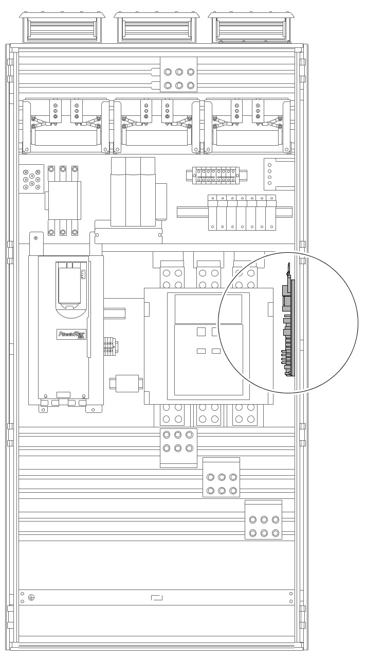 |
Display Code | Display State | Condition Code | Condition Name |
|---|---|---|---|
0 | Flashing | 14001 | Image Watchdog Fault |
0 | Steady | 14070 | Board Over Temperature Alarm |
1 | Flashing | 14002 | Constants Message Invalid |
1 | Steady | 14071 | Board Over Temperature Fault |
2 | Flashing | 14003 | Constants Checksum |
2 | Steady | 14072 | Board Under Temperature Alarm |
3 | Steady | 14073 | Board Under Temperature Fault |
4 | Flashing | 14004 | Nonvolatile Data Checksum Fault |
5 | Flashing | 14005 | Power Supply Undervoltage |
6 | Flashing | 14006 | Precharge Fault |
6 | Steady | 14108 | 240V AC Low |
7 | Flashing | 14007 | MCB Failed to Close or Wiring Bay Overtemp |
7 | Steady | 14109 | 240V AC Loss |
8 | Flashing | 14008 | MCB Failed to Open |
8 | Steady | 14110 | Fused Disconnect Open (MCB open) |
9 | Flashing | 14009 | MCB Aux Mismatch or Wiring Bay Overtemp |
9 | Steady | 14130 | TVSS Open |
10 | Flashing | 14120 | PCC Failed to Close |
11 | Flashing | 14121 | PCC Failed to Open |
12 | Flashing | 14122 | PCC Aux Mismatch |
12 | Steady | 14126 | AC Line Over Voltage |
13 | Flashing | 14123 | MCB Trip Reset |
14 | Flashing | 14124 | MCB Overcurrent |
15 | Flashing | 14010 | 240V AC Loss Fault |
16 | Flashing | 14011 | 240V AC Over Voltage |
17 | Flashing | 14012 | Fused Disconnect Open (MCB closed) |
32 | Steady | 14127 | MCB Life Threshold Exceeded |
33 | Steady | 14128 | PCC Life Threshold Exceeded |
Provide Feedback