Device Definition
To change the definition of a device, select Device definition in
the Overview view.
When you add the module in the project for the first time, Device Definition dialog shows
only Overview view with Channel 0 set to Disabled by default. Depending on what you
choose for the parameter Channel 0, you can have additional parameters.
If you set Channel 0 to Modbus Master, you can see Channel 0 – Modbus Master view. For
more information, see Channel 0 – Modbus Master View.
If you set Channel 0 in Overview view to Modbus Slave, you can see Channel 0 – Modbus
Slave view. For more information, see Channel 0 – Modbus Slave View.
Overview View
Use Overview view in the Device Definition dialog to define a device or change the
device definition.
Device Definition Dialog – Overview View
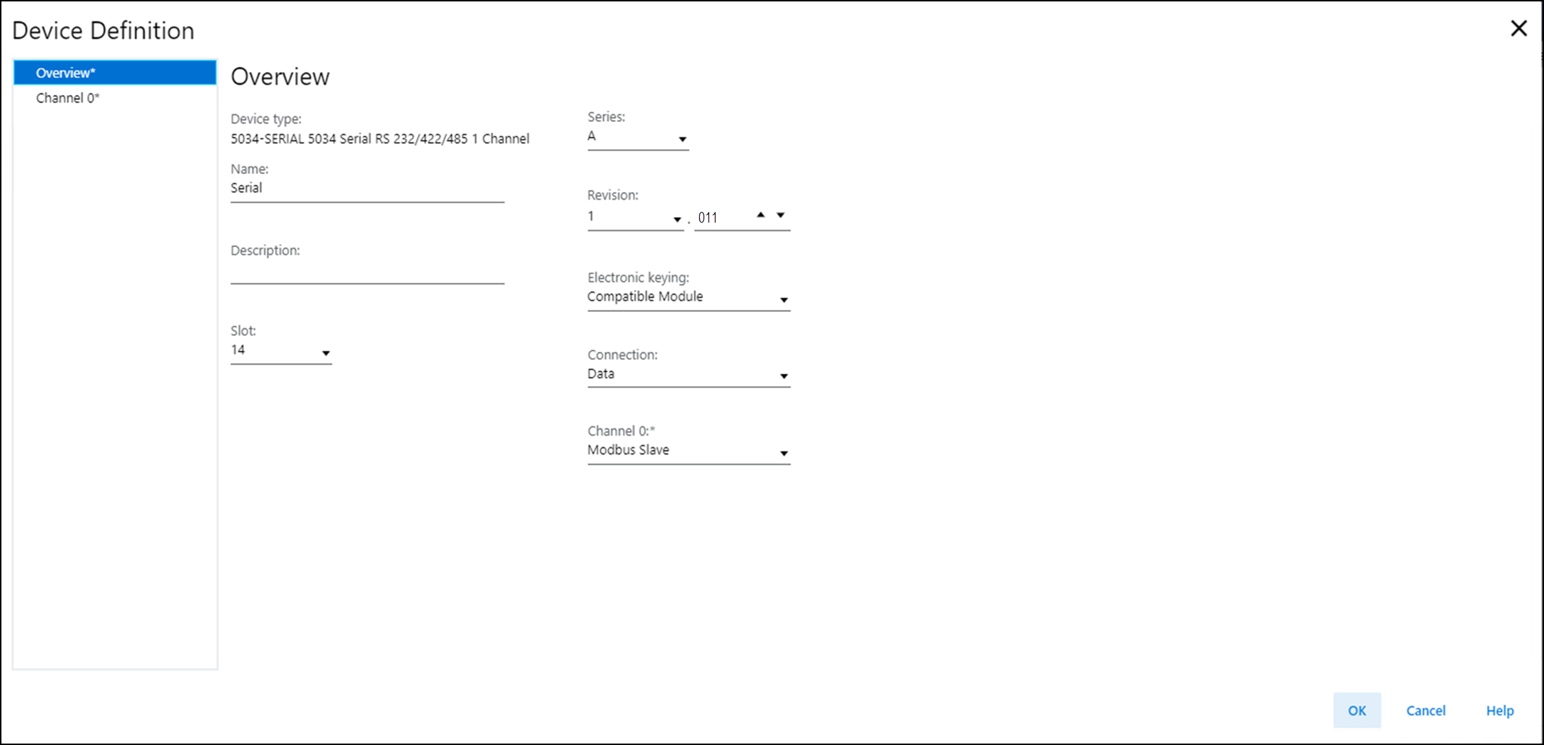
Overview view includes these parameters:
Parameter | Definition | Available Choices |
|---|---|---|
Device Type | Displays the device catalog number and type. | Device-specific |
Name | Enter an IEC 61131 compliant device name. If an invalid character is entered in this field, or if the
name exceeds 40 characters, the software ignores the
character. | All valid values |
Description | Enter the description of the device. | All valid values |
Slot | Specify the slot number where the device resides. Only slots
between 1 and the maximum number of I/O devices are valid
depending on the platform When the device is created, the slot number defaults to the
first available slot position. When the controller is changed to one supporting a smaller
maximum I/O count, the current slot value may no longer be
valid. | 1...32 |
Series | Specifies the series of the device. | Device-specific |
Revision | Specifies the major and minor revisions of the device. The
valid range for minor revision is from 1...255. | Device-specific |
Electronic Keying | Defines the electronic keying used for the device. Electronic
keying compares the device defined in the project to the
installed device. If keying fails, a fault occurs. For detailed information on Electronic keying, see Electronic
Keying in Logix 5000 Control Systems Application Technique,
publication LOGIX-AT001. |
ATTENTION:
Be extremely cautious when using Disable Keying; if
used incorrectly, this option can lead to personal
injury or death, property damage, or economic
loss. We strongly suggest that you do not use Disable
Keying. If you use Disable Keying, you must take full
responsibility for understanding whether the device
being used can fulfill the functional requirements
of the application. |
Connection | Specify the type of data transferred between the device and
controller. | Data (default) |
Channel 0 | Specifies the protocol used by the channel to transmit data
to and receive data from a Serial device. |
For more information, see Table 2. |
Communication Mode | Definition |
|---|---|
Disabled | The channel is unused and no physical connection is enabled
between the controller and the serial module. |
Generic ASCII | A general mode of serial communication where you can define
any user data to be transmitted or received in the
communication. |
Modbus Master | The device sends Modbus queries or write commands to the
slave devices connected to it. |
Modbus Slave | The device operates as a slave to an external master and
waits for commands from the Master. |
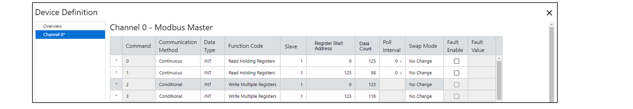
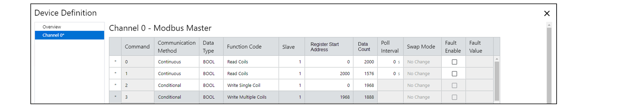
Channel 0 – Modbus Master View
The Modbus Master view allows you to define the Modbus Master device.
Channel 0 – Modbus Master View Example
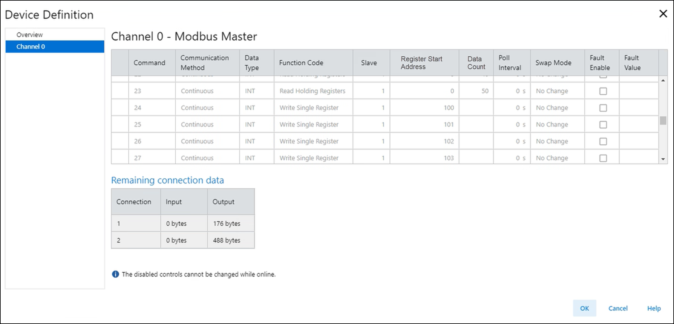
Modbus Master view includes these parameters:
Parameter | Definition | Available Choices | ||||||||||||||||||
|---|---|---|---|---|---|---|---|---|---|---|---|---|---|---|---|---|---|---|---|---|
Command | Displays the index of the command being configured. | 0...49 | ||||||||||||||||||
Communication Method | Specifies the communication method for the command.
TIP:
Parameters are
unavailable when the communication method is
disabled.
|
| ||||||||||||||||||
Data Type | Specifies the data type for the command. |
| ||||||||||||||||||
Function Code | Specifies the function of the command. See Table 4 for the description of each function code choice. | Specifies the function of the command. Valid values are
depend on the Data Type. If Data Type is BOOL:
If Data Type is INT:
If Data Type is REAL:
| ||||||||||||||||||
Slave | Specifies the node address of the Modbus Slave device. | Valid addresses of a specific Modbus Slave device are
1...247. For broadcast command, set the slave to 0.
Broadcast command can only be write commands. | ||||||||||||||||||
Register Start Address | Specifies the start address of the registers being read or
written. | 0...65,535 | ||||||||||||||||||
Data Count | Specifies the number of data of the Data Type being read or
written. If REAL is used, each data uses 2 Registers. The number of consecutive registers read/written are as
follows:
The end address caused by Data Count must not exceed the max
address of 65,535. The end address is calculated as
(Register Start Address + Number of registers - 1). | The valid data length values depend on the Data Type and the
Function Code.
| ||||||||||||||||||
Poll Interval | Specifies the number of seconds between each time the command
is executed when it is in Continuous mode. For example, if the Poll Interval is set at 10, the Modbus
Master waits 10 seconds before executing the command again.
When the Poll Interval is set at 0, the Modbus Master
repeats transmitting the command as fast as possible.
TIP:
This parameter is
unavailable when the Communication Method is
Conditional.
| 0...32,767 | ||||||||||||||||||
Swap Mode | Specifies the arrangement of every 4 bytes of data received
from or transmitted to the Modbus Slave. |
TIP:
A, B, C, and D
represent four adjacent bytes in the
received/transmitted data.
| ||||||||||||||||||
Fault Enable | Determines whether to overwrite the received data with a
Fault Value if the read command fails. Select the checkbox to overwrite the received data with the
Fault Value.
TIP:
This parameter is
unavailable when the Function Code is a write
command.
| – | ||||||||||||||||||
Fault Value | Specifies the value to replace the received data if the read
command fails. | – | ||||||||||||||||||
Connection 1/Connection 2 | Command communication uses Connection 1 by default. If a command data size exceeds the remaining amount of data
available for Connection 1, the command uses Connection 2
instead. | – | ||||||||||||||||||
Input | Shows the amount of read data remaining for that
connection. | – | ||||||||||||||||||
Output | Shows the amount of write data remaining for that
connection. | – |
Data Type | Function Code | Description |
|---|---|---|
BOOL | Read Coils (Function Code 01) | Reads 1...2000 contiguous status of Coils in a slave
device. |
Read Discrete Inputs (Function Code 02) | Reads 1...2000 contiguous status of Discrete Inputs in a
slave device. | |
Write Single Coil (Function Code 05) | Writes a single output to either ON or OFF in a slave
device. | |
Write Multiple Coils (Function Code 15) | Writes 1...1968 contiguous output to either ON or OFF in a
slave device. | |
INT | Read Holding Registers (Function Code 03) | Reads 1...125 contiguous block of INT Holding Registers in a
slave device. |
Read Input Registers (Function Code 04) | Reads 1...125 contiguous block of INT Input Registers in a
slave device. | |
Write Single Register (Function Code 06) | Writes a single Holding Register in a slave device. | |
Write Multiple Registers (Function Code 16) | Writes 1...123 contiguous block of INT Holding Registers in a
slave device. | |
REAL | Read Holding Registers (Function Code 03) | Reads 1...62 contiguous block of REAL Holding Registers in a
slave device. |
Read Input Registers (Function Code 04) | Reads 1...62 contiguous block of REAL Input Registers in a
slave device. | |
Write Multiple Registers (Function Code 16) | Writes 1...61 contiguous block of REAL Holding Registers in a
slave device. |
Master Command List Limitations
Master command list limitations are:
- A maximum of 50 commands can be created. The commands are subject to available connection memory.
- Each Modbus Master supports up to two data connections.
- Connection 1 supports a maximum of 464 bytes of read data and 476 bytes of write data.
- Connection 2 supports a maximum of 472 bytes of read data and 488 bytes of write data.
- Each command uses:
- 2 bytes of input data per holding register or input register read.
- 1 byte of input data per every 1…8 coils or discrete inputs read.
- 2 bytes of output data per holding register written.
- 1 byte of output data per every 1…8 coils written.
- An error message appears when connection memory is exceeded.
Master Command Memory Usage
The following are the examples of master command memory usage:
- Maximum single connection configuration for registers:
- 223 words * 2 bytes/word read = 446 input bytes
- 241 words * 2 bytes/word written = 482 output bytes
- Maximum single connection configuration for coils:
- 3576 bits / 8 bits/byte read = 447 input bytes
- 3856 bits / 8 bits/byte written = 482 output bytes
Channel 0 – Modbus Slave View
The Modbus Slave view allows you to define the Modbus Slave device.
Channel 0 – Modbus Slave View Example
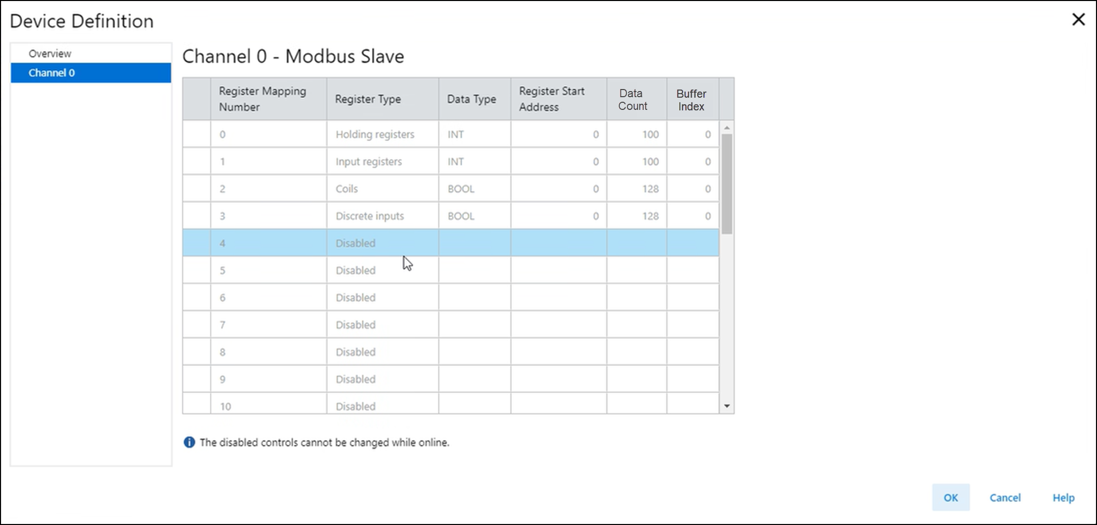
Modbus Slave view includes these parameters:
Parameter | Definition | Available Choices |
|---|---|---|
Register Mapping Number | Displays the Register Mapping Number. | 0...29 |
Register Type | Specifies the type of register.
TIP:
Parameters are
unavailable when the register type is disabled.
|
|
Data Type | Specifies the data type for the register. | Available options are based on the Register Type you
choose. For Coils and Discrete Inputs, available option is:
For Holding Registers and Input Registers, available options
are:
|
Register Start Address | Specifies the start address of the register. | 0...65,535 |
Data Count | Specifies the number of data of the Data Type. | Valid values are depend on the Data Type:
The number of consecutive registers read/written are as
follows:
For any two mappings with the same register type, their
register ranges must not overlap. The register range for
each mapping spans from the Register Start Address to the
end address of the mapping. The end address is calculated as
(Register Start Address + Number of registers - 1). The end address of each mapping must not exceed the max
address of 65,535. |
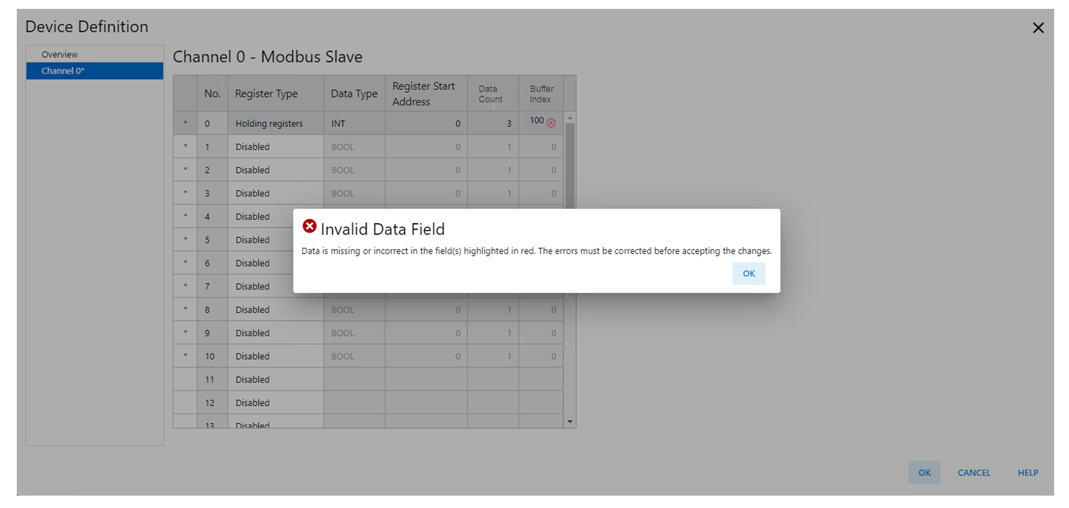
Buffer Index | Specifies the buffer index of the register buffers in input
and/or output tags. These tags are HoldingRegister[y],
Coil[z], InputRegister[y], and DiscreteInput[z] where "y"
and "z" are Buffer Index. |
The number of consecutive buffers occupied by this register
mapping are as follows:
For any two register mappings with the same register type,
their buffer ranges must not overlap. The buffer range spans
from Buffer Index to the end buffer index caused by Data
Count. The end buffer index is calculated as (Buffer Index +
Number of buffers - 1). The end buffer index of each mapping must not exceed the
valid range of Buffer Index defined above. |
Buffer Index Error Example
Modbus Slave Address Table Limits
Up to 30 data point ranges can be created in the Module Slave address table,
subject to available memory:
- 200 byte maximum of Holding Registers (up to 100 INTs or 50 REALs)
- 200 byte maximum of Input Registers (up to 100 INTs or 50 REALs)
- Up to 128 Coils (Data Indexes 0…15 at 8-bit boundaries)
- Up to 128 Discrete inputs (Data Indexes 0…15 at 8-bit boundaries)
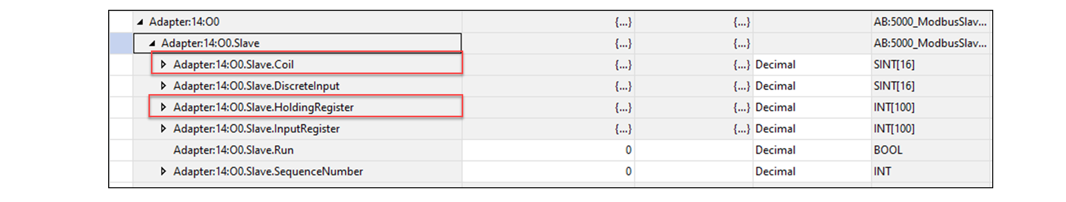
Modbus Slave Data Mapping Example
Modbus Slave Data Mapping Example
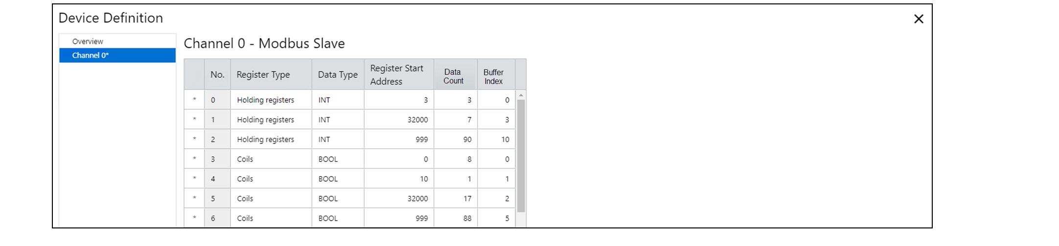
The data represented in Figure 5 can be interpreted
from the module tags as follows:
- v:2:O1.Slave.HoldingRegister[0…2] = 400003…400005
- v:2:O1.Slave.HoldingRegister[3…9] = 432000…432006
- v:2:O1.Slave.HoldingRegister[10…99] = 400999…410088
- v:2:O1.Slave.Coil[0].0…0.7 = 000000…000007
- v:2:O1.Slave.Coil[1].0 = 000010
- v:2:O1.Slave.Coil[2].0…[4].0 = 0320000…032016
- v:2:O1.Slave.Coil[5].0…[15].7 = 000999…001086
Provide Feedback