5034-SERIAL and 5034-SERIALXT Serial RS-232/RS-422/RS-485 1 Channel Module
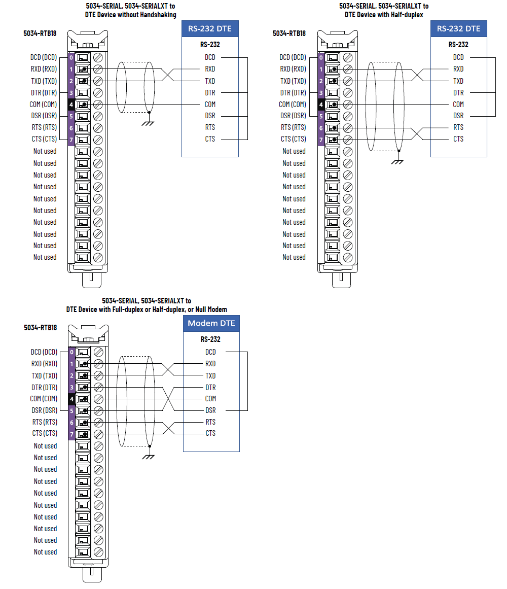
5034-SERIAL and 5034-SERIALXT Wiring Diagram – RS-232 Mode DTE
Device
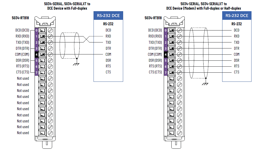
5034-SERIAL and 5034-SERIALXT Wiring Diagram – RS-232 Mode DCE
Device
5034-SERIAL and 5034-SERIALXT Wiring Diagram – RS-485 Mode
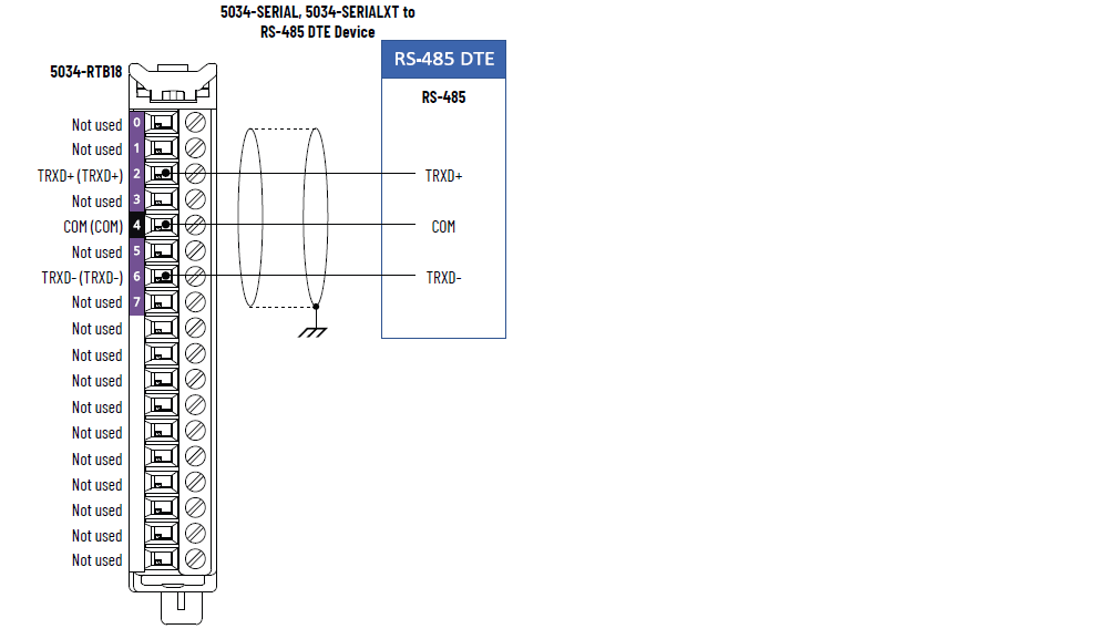
IMPORTANT:
- Place the termination resistor between TRXD+ and TRXD- to implement this wiring.
- The recommended cable to use is Belden 8104.
5034-SERIAL and 5034-SERIALXT Wiring Diagram – RS-422 Mode
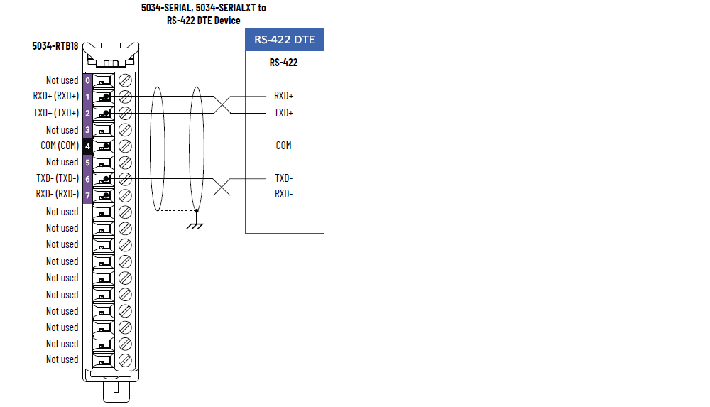
IMPORTANT:
- Place the termination resistor between RXD+ and RXD- to implement this wiring.
- The recommended cable to use is Belden 8104.
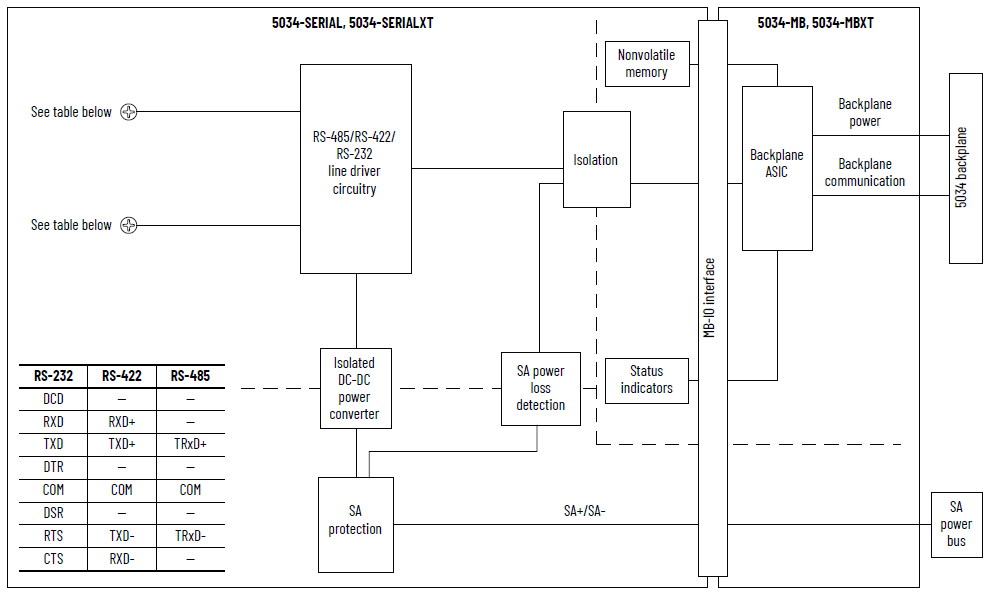
5034-SERIAL and 5034-SERIALXT Functional Block Diagram
Attribute | 5034-SERIAL, 5034-SERIALXT |
|---|---|
Operating modes | Generic ASCII Modbus RTU Modbus ASCII |
Serial input signal voltage range | +3…+25V DC regarding signal ground (SG) 0, Asserted, ON,
Space, Active -3…-25V DC regarding signal ground (SG) 1, Deasserted, OFF,
Mark, Inactive |
Handshaking | RTS/CTS hardware handshake always enabled RTS/CTS user-controllable |
Supported communication rate (bps) | 1200, 2400, 4800, 9600, 19200 (Default), 38400, 57600,
115200 |
Attribute | 5034-SERIAL, 5034-SERIALXT |
|---|---|
Number of inputs | One full-duplex (RS-232, RS-422)/half-duplex (RS-485) |
Voltage category | 24V DC source |
SA power voltage, nom | 24V DC |
SA power voltage range | 10…30V DC |
SA power current, nom | 20 mA |
SA power current, max | 30 mA |
SA power current at no load | 15 mA |
SA reverse polarity protection | Yes |
Power dissipation, max (1) | 0.35 W |
Thermal dissipation, max (1) | 1.20 BTU/hr |
Isolation voltage | 250V (continuous), Basic Insulation Type, System to SA
power 250V (continuous), Basic Insulation Type, SA power to
Communication channel 250V (continuous), Basic Insulation Type, System to
Communication channel |
RIUP support | Yes |
Electronic keying | Electronic keying via programming software |
RTB key positions (slot) | 3, 5, 11 |
RTB supported | 5034-RTB18, 5034-RTB18S |
Wiring category (2) | 2 - Signal ports 2 - Power ports |
Wiring specification | See Wiring Specifications for Removable Terminal Blocks in
the PointMax I/O System Specifications Technical Data,
publication 5034-TD001 |
Indicators | 1 green/red module status indicator 1 green/red SA power status indicator 2 yellow/red I/O status indicators |
Dimensions (HxWxD), approx | 123.6 x 15.0 x 66.4 mm (4.87 x 0.59 x 2.61 in.) |
Weight, approx | 45.0 g (1.59 oz.) – 5034-SERIAL 47.0 g (1.66 oz.) – 5034-SERIALXT |
Enclosure type | None (Open-style) |
North American temp code | T4 |
UKEX/ATEX temp code | T4 |
IECEx temp code | T4 |
(1) Value is measured at 60 °C (140 °F). Power dissipation
varies with temperature. (2) Use this Conductor Category information for planning
conductor routing. See the Industrial Automation Wiring and
Grounding Guidelines, publication 1770-4.1. Use this
Conductor Category information for planning conductor
routing as described in the appropriate System Level
Installation Manual. | |
Provide Feedback