Device Definition
To change the definition of a device, select Device definition in
the Overview view.
Device Definition dialog has following views to define your device and configure the
channel operating mode:
- Overview View
- Channel Assignments View
Device Definition - Overview View
The Device Definition - Overview View appears first when you create a module. Use
this view to define the module.
If you have already created the module and want to modify these parameters, go to
Overview → Device definition, then select Overview tab.
IMPORTANT:
When controller status is online, you
can only change the parameters Name, Revision (only minor revision), and
Electronic keying from this view.
Device Definition - Overview View Example
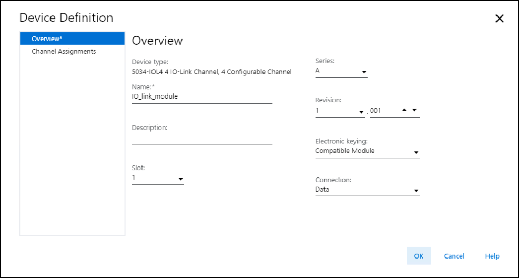
Overview view includes these parameters:
Parameter | Definition | Available Choices |
|---|---|---|
Device Type | Displays the device catalog number and type. | Device-specific |
Name | Enter an IEC 61131 compliant device name. If an invalid character is entered in this field, or if the
name exceeds 40 characters, the software ignores the
character. | All valid values |
Description | Enter the description of the device. | All valid values |
Slot | Specify the slot number where the device resides. Only slots
between 1 and the maximum number of I/O devices are valid
depending on the platform. When the device is created, the slot number defaults to the
first available slot position. When the controller is changed to one supporting a smaller
maximum I/O count, the current slot value may no longer be
valid. | 1...32 |
Series | Specifies the series of the device. | Device-specific |
Revision | Specifies the major and minor revisions of the device. The
valid range for minor revision is from 1…255. | Device-specific |
Electronic Keying | Defines the electronic keying used for the device. Electronic
keying compares the device defined in the project to the
installed device. If keying fails, a fault occurs. For detailed information on Electronic keying, see Electronic
Keying in Logix 5000 Control Systems Application Technique,
publication LOGIX-AT001 |
ATTENTION:
Be extremely cautious when using Disable Keying; if used
incorrectly, this option can lead to personal injury or
death, property damage, or economic loss. We strongly suggest that you do not use Disable
Keying. If you use Disable Keying, you must take full
responsibility for understanding whether the device
being used can fulfill the functional requirements of
the application. |
Connection | Specify the type of data transferred between the device and
controller. |
|
Device Definition - Channel Assignments View
Use this view to configure the channel operating mode. Not all channel modes can be
configured for each channel.
Device Definition - Channel Assignments View Example
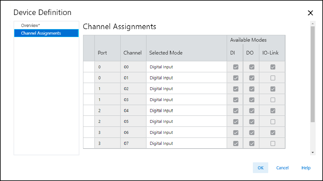
Channel Assignments view parameters:
Parameter | Definition | Available Choices |
|---|---|---|
Port | Displays the module port numbers. | Not configurable |
Channel | Displays the module channel numbers | Not configurable |
Selected Mode | Displays the mode for the channel. |
|
Available Modes | Displays the different types of channel modes supported by
each channel.
| Not configurable |
Provide Feedback