5034-IOL4 and 5034-IOL4XT IO-Link Master 4-channel Module
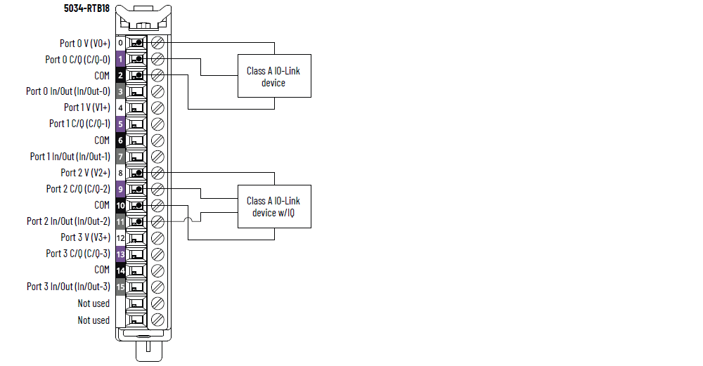
5034-IOL4 and 5034-IOL4XT Wiring Diagram – IO-Link Mode
|
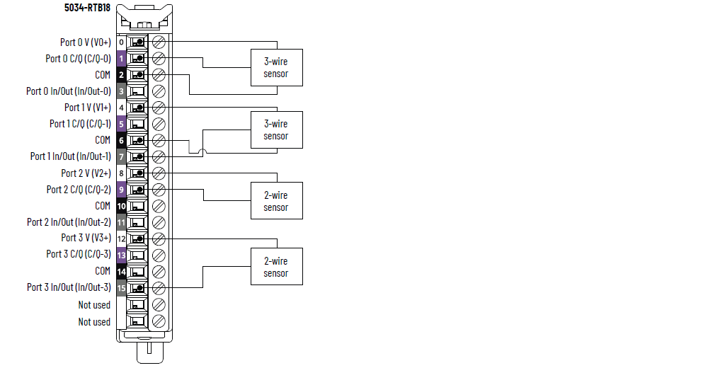
5034-IOL4 and 5034-IOL4XT Wiring Diagram – DI Mode
|
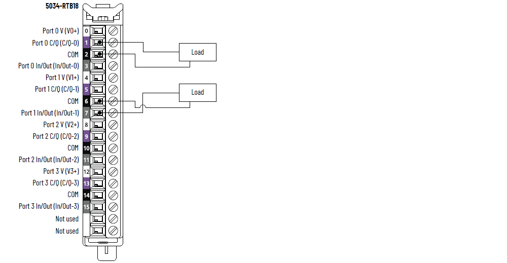
5034-IOL4 and 5034-IOL4XT Wiring Diagram – DO Mode
|
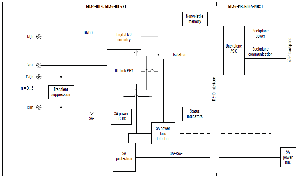
5034-IOL4 and 5034-IOL4XT Functional Block Diagram
Attribute | 5034-IOL4, 5034-IOL4XT |
|---|---|
Number of ports | 4 Class A ports |
Communication speed | 4.8 Kbps, 38.4 Kbps, 230.4 Kbps |
Voltage rating | 20…30V DC |
V+ current rating, per port, max | 0.5 A |
IO-Link device cable length, max | 20 m (66 ft) |
IO-Link Protocol version | Versions 1.0 and 1.1 |
Attribute | 5034-IOL4, 5034-IOL4XT |
|---|---|
On-state voltage range Channel 0, 2, 4, 6 | 11…30V DC – C/Q (in SIO mode) |
On-state voltage range Channel 1, 3, 5, 7 | 10…30V DC – I/Q |
On-state current, min Channel 0, 2, 4, 6 | 2 mA – C/Q (in SIO mode) |
On-state current, min Channel 1, 3, 5, 7 | 2 mA – I/Q |
On-state current, nom Channel 0, 2, 4, 6 | 2.5 mA – C/Q (in SIO mode) |
On-state current, nom Channel 1, 3, 5, 7 | 2.3 mA – I/Q |
On-state current, max Channel 0, 2, 4, 6 | 6.6 mA – C/Q (in SIO mode) |
On-state current, max Channel 1, 3, 5, 7 | 5 mA – I/Q |
Off-state voltage, max Channel 0, 2, 4, 6 | 5V DC – C/Q (in SIO mode) |
Off-state voltage, max Channel 1, 3, 5, 7 | 5V DC – I/Q |
Off-state current, max Channel 0, 2, 4, 6 | 1.5 mA – C/Q (in SIO mode) |
Off-state current, max Channel 1, 3, 5, 7 | 1.5 mA – I/Q |
Input impedance, min | 1.6 kΩ @ 11V DC – C/Q (in SIO mode) 2 kΩ @ 10V DC – I/Q |
Input impedance, nom | 9.6 kΩ @ 24V DC – C/Q (in SIO mode) 10.4 kΩ @ 24V DC – I/Q |
Input impedance, max | 15 kΩ @ 30V DC – C/Q (in SIO mode) 15 kΩ @ 30V DC – I/Q |
Input delay time (screw to backplane), max Channel 0, 2, 4, 6 Off-to-On On-to-Off | 900 µs |
Input delay time (screw to backplane), max Channel 1, 3, 5, 7 Off-to-On On-to-Off | 60 µs |
Input min pulse width Channel 0, 2, 4, 6 Off-to-On On-to-Off | 1 ms |
Input min pulse width Channel 1, 3, 5, 7 Off-to-On On-to-Off | 0.125 ms |
Input filter time Channel 0, 2, 4, 6 Off-to-On On-to-Off | 0 µs, 2 ms (Default), 5 ms, 10 ms, 20 ms, 50 ms |
Input filter time Channel 1, 3, 5, 7 Off-to-On On-to-Off | 0 µs, 100 µs, 200 µs, 500 µs (Default), 1 ms, 2 ms, 5 ms, 10
ms, 20 ms, 50 ms The 0 µs setting is embedded with a 10 µs filter. |
Simple counters, counter frequency Channel 0, 2, 4, 6 | 0…f max = 500 Hz |
Simple counters, counter frequency Channel 1, 3, 5, 7 | 0…f max = 4000 Hz |
Timestamp of inputs (sequence of events) Channel 0, 2, 4, 6 | Yes, ±500 µs accuracy |
Timestamp of inputs (sequence of events) Channel 1, 3, 5, 7 | Yes, ±10 µs accuracy |
Events | Yes |
Pattern matching | Yes |
Attribute | 5034-IOL4, 5034-IOL4XT |
|---|---|
On-state voltage range Channel 0, 2, 4, 6 | 20…30V DC – C/Q (in SIO mode) |
On-state voltage range Channel 1, 3, 5, 7 | 20…30V DC – I/Q |
On-state voltage drop, max Channel 0, 2, 4, 6 | 0.6V DC – C/Q (in SIO mode) |
On-state voltage drop, max Channel 1, 3, 5, 7 | 0.3V DC – I/Q |
On-state current per channel, max Channel 0, 2, 4, 6 | 250 mA – C/Q (in SIO mode) |
On-state current per channel, max Channel 1, 3, 5, 7 | 500 mA – I/Q |
Off-state leakage current per point, max Off-state open wire detection disabled Channel 1, 3, 5, 7 only | 0.1 mA |
Off-state leakage current per point, max (1) Off-state open wire detection enabled Channel 1, 3, 5, 7 only | 0.5 mA |
Surge current per output, max Channel 1, 3, 5, 7 | 1 A for 10 ms, repeatable every 3 s |
Output current rating per module, max | 3 A |
Output delay time (backplane to screw), max Channel 0, 2, 4, 6 Off-to-On On-to-Off | 1 ms |
Output delay time (backplane to screw), max Channel 1, 3, 5, 7 Off-to-On On-to-Off | 0.15 ms |
Open load detection diagnostics Channel 1, 3, 5, 7 only | Yes, configurable (Default is off) |
Output short circuit/overload detection Channel 0, 2, 4, 6 | Yes |
Output short circuit/overload detection Channel 1, 3, 5, 7 | Yes |
(1) Recommended Loading Resistor - To limit the effects of
leakage current through solid-state outputs, you can connect
a loading resistor in parallel with your load. For 24V DC
operation, use a 5.6 kΩ, 0.5 W resistor for transistor
operation. | |
Attribute | 5034-IOL4, 5034-IOL4XT |
|---|---|
Number of inputs/outputs | 8 channels, configurable, inclusive of 4x C/Q channels
configured to SIO mode, sinking input, sourcing output |
SA power voltage, nom | 24V DC |
SA power voltage range | 20…30V DC |
SA power current, nom | 3.2 A |
SA power current, max | 3.3 A |
SA power current at no load | 14 mA |
SA reverse polarity protection | Yes |
Power dissipation, max (1) | 1.04 W |
Thermal dissipation, max (1) | 3.55 BTU/hr |
Isolation voltage | 250V (continuous), Basic Insulation Type, System to Field No isolation between SA power and channels No isolation between individual channels |
RIUP upport | Yes |
CIP Sync | Yes, slave only ordinary clock |
Electronic keying | Electronic keying via programming software |
RTB key positions (slot) | 3, 6, 12 |
RTB supported | 5034-RTB18, 5034-RTB18S |
Wiring category (2) | 2 - Signal ports 2 - Power ports |
Wiring specification | See Wiring Specifications for Removable Terminal Blocks in
the PointMax I/O System Specifications Technical Data,
publication 5034-TD001 |
Indicators | 1 green/red module status indicator 1 green/red SA power status indicator 8 yellow/red I/O status indicators |
Dimensions (HxWxD), approx | 123.6 x 15.0 x 66.4 mm (4.87 x 0.59 x 2.61 in.) |
Weight, approx | 48.0 g (1.69 oz.) – 5034-IOL4 51.0 g (1.80 oz.) – 5034-IOL4XT |
Enclosure type | None (Open-style) |
North American temp code | T4 |
UKEX/ATEX temp code | T4 |
IECEx temp code | T4 |
(1) Value is measured at 60 °C (140 °F). Power dissipation
varies with temperature. (2) Use this Conductor Category information for planning
conductor routing. See the Industrial Automation Wiring and
Grounding Guidelines, publication 1770-4.1. Use this
Conductor Category information for planning conductor
routing as described in the appropriate System Level
Installation Manual. | |
Provide Feedback