5034-ENC and 5034-ENCXT HSC/SSI Encoder 1 Channel Module
5034-ENC and 5034-ENCXT Wiring Diagram – HSC/Incremental Encoder
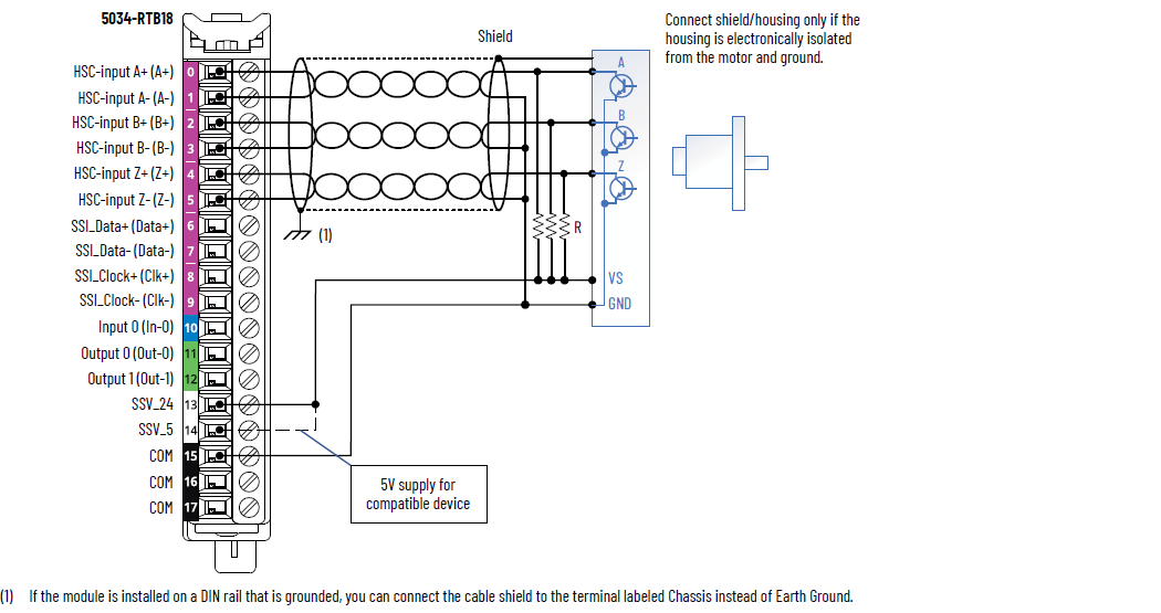
IMPORTANT:
When using the module in HSC mode, do not connect wiring to the SSI terminals
(Data, Clk).
IMPORTANT:
External resistors, as indicated by the “R” in the diagram, are required if
they are not internal to the encoder. The pull-up resistor (R) value depends
on the power supply value.
To calculate the maximum resistor value, use the following formula:
R = VDC - V
min
/Imin
Where:
- R = Maximum pull-up resistor value
- VDC = Power supply voltage (either SSV_24 or SSV_5)
- Vmin= 3.0V DC
- Imin= 2.5 mA
Supply By | Power Supply Voltage (V DC) | Pull-up Resistor Value (R), Max
(Ω) (1) |
|---|---|---|
SSV_24 | 10 | 2800 |
24 | 8400 | |
30 | 10,800 | |
SSV_5 | 5 | 800 |
(1) Resistance values can change, depending on your
application. The minimum resistor (R) value depends
on the current-sinking capability of the
encoder. | ||
5034-ENC and 5034-ENCXT Wiring Diagram – SSI/Absolute Encoder
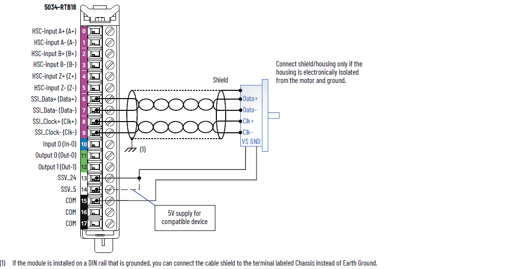
IMPORTANT:
When using the module in SSI mode, do
not connect wiring to the HSC terminals (A, B, Z).
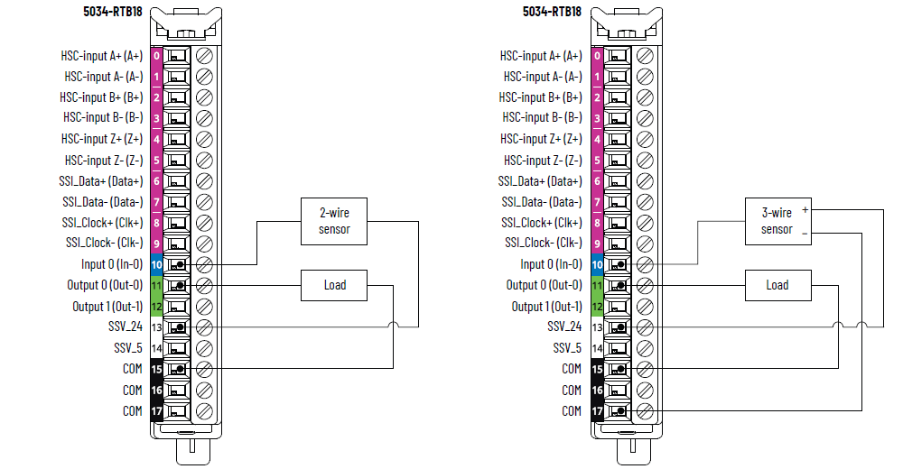
5034-ENC and 5034-ENCXT Wiring Diagram – Input/Output
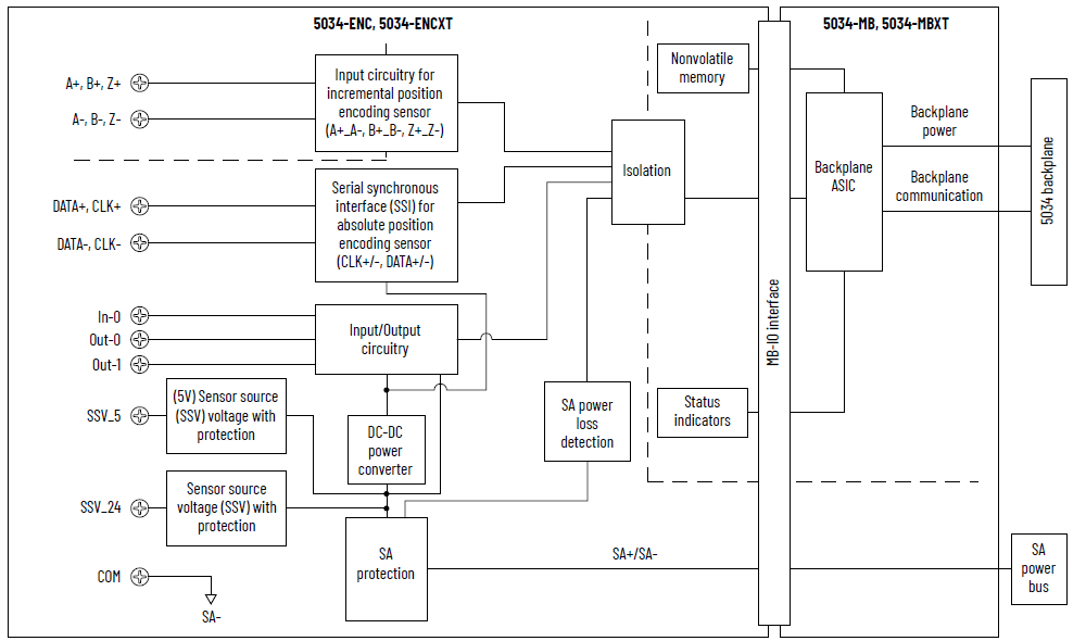
5034-ENC and 5034-ENCXT Functional Block Diagram
Attribute | 5034-ENC, 5034-ENCXT |
|---|---|
On-state voltage range Channel A, B, Z | 3…32V DC |
On-state current, min Channel A, B, Z | 2.5 mA @ 3V DC |
On-state current, nom Channel A, B, Z | 4.0 mA @ 24V DC |
On-state current, max Channel A, B, Z | 8.0 mA @ 32V DC |
Off-state voltage, max Channel A, B, Z | 1.5V DC |
Off-state current, max Channel A, B, Z | 0.5 mA |
Input pulse width, min Off-to-On On-to-Off | 125 ns |
Input filter time Off-to-On On-to-Off | 0 ns, 100 ns, 200 ns, 500 ns, 1 µs, 2 µs, 5 µs (Default for
Input A and Input B), 10 µs, 20 µs, 50 µs, 100 µs, 200 µs,
500 µs, 1 ms (Default for Input Z), 2 ms, 5 ms, 10 ms, 20
ms, 50 ms |
Phase separation, min | 100 ns |
Input pulse frequency, max | 1.0 MHz |
Input pulse frequency, min | 0.1 Hz |
Attribute | 5034-ENC, 5034-ENCXT |
|---|---|
SSI mode encoder type | Any absolute encoder supporting standard SSI protocol including
linear, rotary, and optical distance measuring devices in
MSB-aligned data format The physical interface for clock and data signals is RS-422. |
SSI data rate supported | 125 kHz (Default), 250 kHz, 500 kHz, 1 MHz, 2 MHz |
SSI bits per word supported | 2…31 bits 13 bits (Default) |
SSI word delay time | 16…65,535 µs 64 µs (Default) |
SSI code type supported | Binary, Gray (Gray to binary conversion supported) |
SSI direction | Increasing or decreasing SSI count indication |
SSI data comparator | Up to four window comparators |
SSI data latching | Supported using In-0 input |
SSI cable type | UL CM/AWM 2464/CSA Type CMG FT4 or similar cable utilizing
shielded twisted pairs for D+/- and C+/- connections. See sensor
manufacturer for actual cable required for the SSI sensor under
use. In-0 input can be separate from SSI cable. |
SSI cable length, max | Depending on the desired SSI data rate: 125 kHz – 320 m (1050 ft) 250 kHz – 160 m (525 ft) 500 kHz – 60 m (195 ft) 1 MHz – 20 m (65 ft) 2 MHz – 8 m (25 ft) |
Attribute | 5034-ENC, 5034-ENCXT |
|---|---|
On-state voltage range | 10…30V DC |
On-state current, min | 2.0 mA |
On-state current, nom | 4.5 mA |
On-state current, max | 5.0 mA |
Off-state voltage, max | 5V DC |
Off-state current, max | 1.5 mA |
Input impedance, min | 2 kΩ @ 10V DC |
Input impedance, nom | 5.3 kΩ @ 24V DC |
Input impedance, max | 15 kΩ @ 30V DC |
Input delay time (screw to backplane), max Off-to-On On-to-Off | 150 µs |
Input pulse width, min Off-to-On On-to-Off | 10 µs |
Input filter time Off-to-On On-to-Off | 0 ns, 10 µs, 20 µs, 50 µs, 100 µs, 200 µs, 500 µs, 1 ms
(Default), 2 ms, 5 ms, 10 ms, 20 ms, 50 ms |
Timestamp of inputs (sequence of events) | Not supported |
Attribute | 5034-ENC, 5034-ENCXT |
|---|---|
On-state voltage range | 10…30V DC |
On-state voltage drop, max | 0.25V DC |
On-state current per point, min | 1.0 mA |
Off-state voltage, max | 5V DC with 1 mA min load |
Off-state leakage current per point, max (1) | 0.5 mA |
Output current rating per channel, max | 0.5 A |
Output current rating per module, max | 1 A |
Surge current per point, max | 1.2 A for 10 ms, repeatable every 3 s |
Inductive load allowed, max | 1.2 H |
Output clamping voltage for inductive load when turn off | (SA voltage + VCL)…0 VCL value: Minimum is -63V, Typical is -55V, Maximum is
-49V |
Output delay time (backplane to screw), max Off-to-On On-to-Off | 150 µs |
Open load detection diagnostics | Not supported |
Output short circuit/overload detection | Yes |
Output short circuit/overload protection | Yes |
Pilot duty rating | 1.2 A inrush current, 0.5 A rated current, DC-14 |
Output states in program mode per point | Hold Last State On Off (Default) Local Control |
Output states in communication fault mode per point | Hold Last State On Off (Default) Local Control |
Duration of fault mode per point | 1 s 2 s 5 s 10 s Forever (Default) |
Output final state after fault mode per point | On Off (Default) |
(1) Recommended loading resistor - To limit the effects of
leakage current through solid-state outputs, you can connect
a loading resistor in parallel with your load. For 24V DC
operation, use a 5.6 kΩ, 0.5 W resistor for transistor
operation. | |
Attribute | 5034-ENC, 5034-ENCXT |
|---|---|
Number of HSC | 1 group of A+/A-, B+/B-, and Z+/Z- |
Number of SSI | 1 group of Data+/Data- and Clock+/Clock- |
Number of inputs | 1 channel, sinking |
Number of outputs | 2 channels, sourcing |
SA power voltage, nom | 24V DC |
SA power voltage range | 10…30V DC |
SA power current, nom | 1.6 A |
SA power current, max | 1.7 A |
SA power current at no load | 12 mA |
SA reverse polarity protection | Yes |
SSV voltage range, SSV_24 | Follow SA power supply |
SSV voltage range, SSV_5 | 5V (±5%) |
SSV current, SSV_24, max | 500 mA |
SSV current, SSV_5, max | 300 mA |
SSV short-circuit protection, SSV_24 | Yes |
SSV short-circuit protection, SSV_5 | Yes |
Power dissipation, max (1) | 1.22 W |
Thermal dissipation, max (1) | 4.16 BTU/hr |
Isolation voltage | 250V (continuous), Basic Insulation Type, System to Field 250V (continuous), Basic Insulation Type, HSC input to other
Field side 250V (continuous), Basic Insulation Type, HSC input to
System No isolation between SA power and Digital input/output
points No isolation between SA power and SSI ports No isolation between SA power and SSV_24/SSV_5 No isolation between individual Digital input/output
points |
RIUP support | Yes |
CIP Sync | Slave only ordinary clock |
Electronic keying | Electronic keying via programming software |
RTB key positions (slot) | 3, 7, 12 |
RTB supported | 5034-RTB18, 5034-RTB18S |
Wiring category (2) | 2 - Signal ports 2 - Power ports |
Wiring specification | See Wiring Specifications for Removable Terminal Blocks in
the PointMax I/O System Specifications Technical Data,
publication 5034-TD001 |
Indicators | 1 green/red module status indicator 1 green/red SA power status indicator 5 yellow/red I/O status indicators 1 yellow I/O status indicator |
Dimensions (HxWxD), approx | 123.6 x 15.0 x 66.4 mm (4.87 x 0.59 x 2.61 in.) |
Weight, approx | 45.0 g (1.59 oz.) – 5034-ENC 47.0 g (1.66 oz.) – 5034-ENCXT |
Enclosure type | None (Open-style) |
North American temp code | T4 |
UKEX/ATEX temp code | T4 |
IECEx temp code | T4 |
(1) Value is measured at 60 °C (140 °F). Power dissipation
varies with temperature. (2) Use this Conductor Category information for planning
conductor routing. See the Industrial Automation Wiring and
Grounding Guidelines, publication 1770-4.1. Use this
Conductor Category information for planning conductor
routing as described in the appropriate System Level
Installation Manual. | |
Provide Feedback