Safety Input Modules in CIP Safety Systems
The following apply to the safety inputs:
- You can connect safety devices, such as Emergency Stop Push Button, gate switches, and safety light curtains.
- An external wiring short-circuit check is possible when inputs are wired in combination with test outputs. The module must be wired in combination with test outputs when this function is used.
- Independently adjustable on and off delays are available per channel.
- If you configure inputs as Safety Pulse Test, you must choose a test source.
- Diagnostics. See Point Diagnostics.
- Safety input points are configured as the following:
- Not Used
- Safety Pulse Test
- Safety
The following apply to the test outputs:
- Test outputs can be configured as the following:
- Not Used
- Standard Output
- Pulse Test
- Power Supply
- Muting Lamp
- Separate test outputs are provided for short-circuit detection of a safety input (or inputs).
- Can supply 24V DC power to devices, such as safety sensors.
Use Test Output with a Safety Input
A test output can be used in combination with a safety input for short circuit and
cross-channel fault detection.
Configure the test output as a pulse test source and associate it to a specific
safety input. The associated safety input must use a Point Mode = Safety Pulse
Test.
One test output can be assigned to a maximum of four safety inputs.
Test Pulse in a Cycle

On the safety input modules, the pulse width (X) is less than 700 μs; the pulse
period (Y) is less than 524 ms.
When an external contact is closed, a test pulse is output from the test output
terminal to diagnose the field wiring and input circuitry. By using this function,
short circuits between inputs and power supply (positive), and between input signal
lines can be detected. However, a short circuit between two input channels cannot be
detected if these two channels correspond to the same Test Output. For example, you
associate Test Output 0 to Safety Input 0 and 7. If these two channels short
circuit, it cannot be detected.
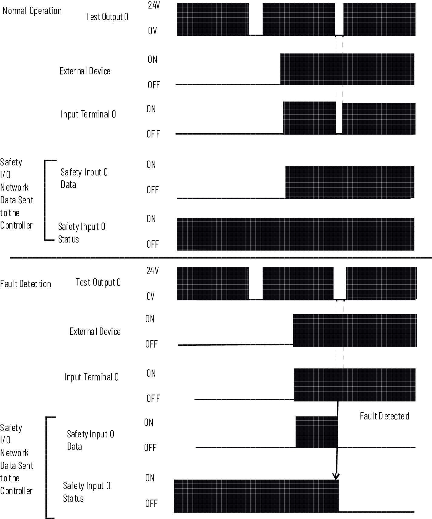
Short Circuit Between Input Signal Lines

Single-channel Mode
If an error is detected on the input channel, Safety Input Data and Safety Input
Status change to the off state.
Normal Operation and Fault Detection (Not to Scale)
Safety Input Fault Reset
The I/O channel supports a module-level user-configurable ‘Latch Fault until Reset
via Output Tag’ mode and recovers from a Safety Input Short Circuit fault.
TIP:
Other types of Safety Input faults are non-recoverable. You must cycle power
to the module.
Latch Fault until Reset via Output Tag mode is Enabled
When Latch Fault mode is Enabled, the I/O channel holds safety input fault
indications until it checks that the fault is removed. If the fault is removed, the
channel clears the fault status only upon detecting that the ResetFault in its
consume assembly channel sees a transition from 0 to 1.
Latch Fault until Reset via Output Tag mode is Disabled
When Latch Fault mode is Disabled (default), the I/O channel holds safety input fault
indications for 1 second until it checks if the fault is removed. If the fault is
removed, the channel clears the fault status only upon detecting the safety input is
low on the screw. If not, the channel continues to check if the fault is
removed.
Safety Input Delay Time
You can increase the time that it takes for an input point to transition from On to
Off and Off to On. The increase in time is a delay of the signal from the module to
the controller.
The delay time is added to the RPI. For example, if you set the RPI at 10 ms and use
an input delay time of 2 ms, the signal from the module to the controller is 12
ms.
When chattering or low frequency noise coupling is present on the input signal, an
increase in the time it takes to transition from one state to another improves noise
immunity within a signal.
Description | Transition Delay Times | Diagram |
|---|---|---|
An input signal is treated as Logic 0 during the Off to On
delay time after the rising edge of the input contact. The input turns on only if the input contact remains on after
the Off to On delay time has elapsed. This setting help
prevent rapid changes of the input data due to contact
bounce. |
| 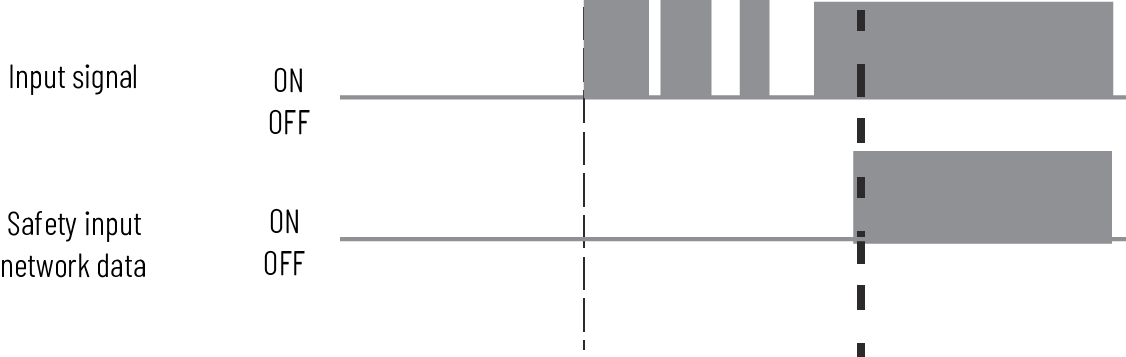 |
Description | Transition Delay Times | Diagram |
|---|---|---|
An input signal is treated as Logic 1 during the On to Off delay
time after the falling edge of the input contact. The input turns off only if the input contact remains off after
the On to Off delay time has elapsed. This setting helps to
prevent rapid changes of the input data due to contact
bounce. |
| 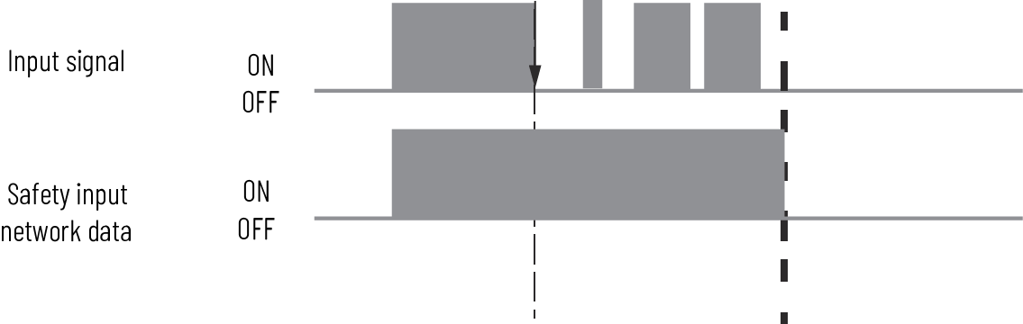 |
Provide Feedback