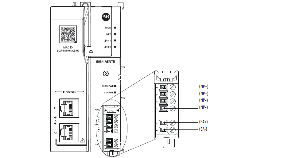
5034-AENTR and 5034-AENTRXT EtherNet/IP Adapter
5034-AENTR and 5034-AENTRXT Wiring Diagram
Attribute | 5034-AENTR, 5034-AENTRXT |
|---|---|
Number of I/O modules supported | 32 A 5034-EXP or 5034-EXPXT is required when using more than 16 I/O
modules. |
Number of MB supported | 16 for 18…30V DC 8 for 10…18V DC |
MP voltage, nom | 24V DC SELV |
MP voltage range | 10…30V DC SELV |
MP current, nom | 0.6 A @ 24V DC |
MP current, max | 850 mA @ 10V DC (8 MB) 800 mA @ 18V DC (16 MB) 500 mA @ 30V DC (16 MB) |
Voltage and current ratings, MP inrush, max | 6 A for 10 ms @ 24V DC SELV |
Voltage and current ratings, SA | 10…30V DC SELV, 10 A Do not exceed 10 A current draw at the SA power RTB |
Voltage and current ratings, backplane | 16V DC, 300 mA max (8 MB) 16V DC, 600 mA max (16 MB) |
SA power current at no load | 2 mA |
Power dissipation, max | 3.6 W |
Thermal dissipation, max | 12.3 BTU/hr |
Isolation voltage | 250V (continuous), Basic Isolation, SA to backplane 250V (continuous), Basic Isolation, SA to MP 250V (continuous), Basic Isolation, Ethernet port to SA 60V (continuous), Basic Isolation, MP to backplane 60V (continuous), Basic Isolation, Ethernet port to MP 60V (continuous), Basic Isolation, Ethernet port to
backplane No isolation between Ethernet ports |
RTB supported | An RTB and end cap ships with the adapter. You can order additional screw-type (5034-AENRTB-QTY5) and
push-in spring-type (5034-AENRTBS-QTY5) RTBs separately. |
Wiring category (1) | 2 - Power ports 2 - Ethernet ports |
Wiring specification | |
Indicators | 1 green/red module status indicator 1 green/red network status indicator 2 green/red network connection status indicators 1 green module power status indicator 1 green SA power status indicator |
Dimensions (HxWxD), approx | 131.74 x 62.65 x 76 mm (5.18 x 2.46 x 2.99 in.) |
Weight, approx | 200 g (7.05 oz.) – 5034-AENTR 202 g (7.13 oz.) – 5034-AENTRXT |
Enclosure type | None (Open-style) |
North American temp code | T4 |
UKEX/ATEX temp code | T4 |
IECEx temp code | T4 |
(1) Use this Conductor Category information for planning
conductor routing. See the Industrial Automation Wiring and
Grounding Guidelines, publication 1770-4.1. Use this
Conductor Category information for planning conductor routing as
described in the appropriate System Level Installation
Manual. | |
Provide Feedback