5034-OB8 and 5034-OB8XT Digital 8 Output Modules
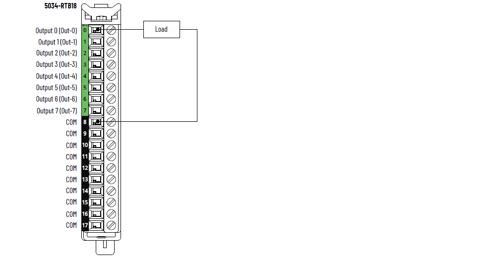
5034-OB8 and 5034-OB8XT Wiring Diagram
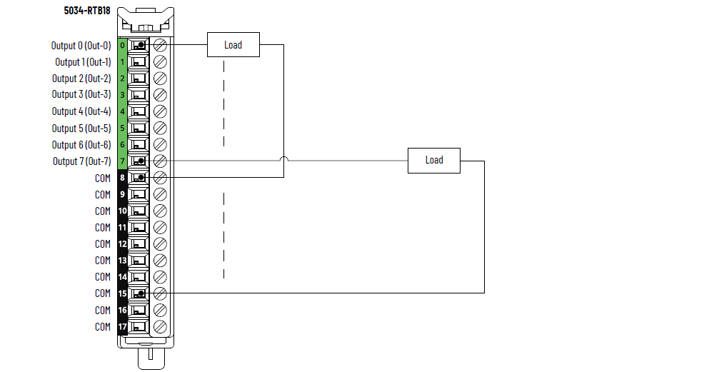
5034-OB8 and 5034-OB8XT Wiring Diagram – Individual Load Return Wiring on
COM Pins
5034-OB8 and 5034-OB8XT Wiring Diagram – Star-connected Load Return
Wiring on COM Pins
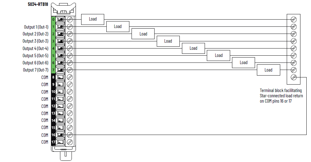
IMPORTANT:
Use only COM pins 16 and 17 for the
star-connected load return wiring.
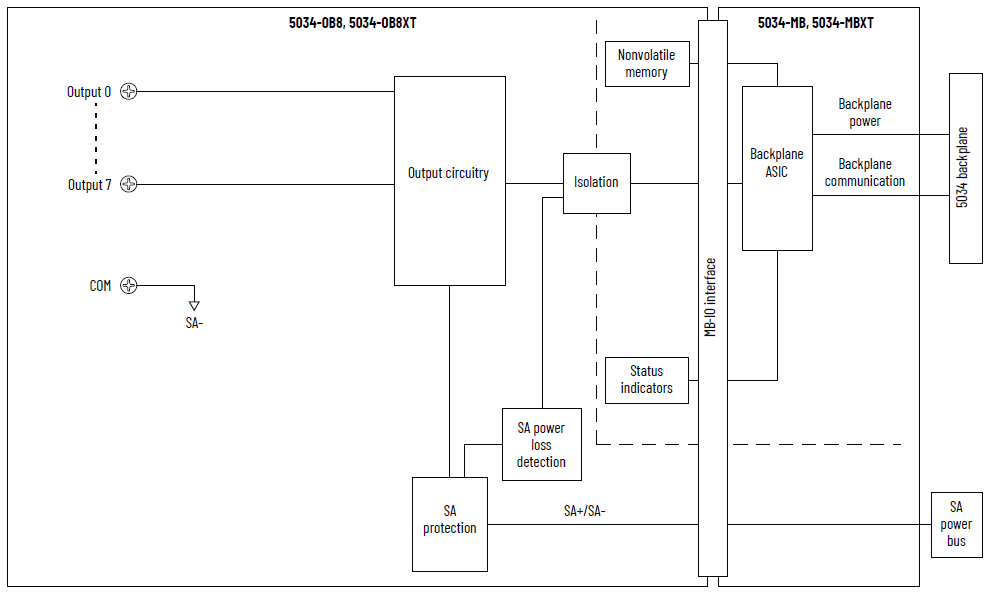
5034-OB8 and 5034-OB8XT Functional Block Diagram
Attribute | 5034-OB8, 5034-OB8XT |
|---|---|
On-state voltage range | 10…30V DC |
On-state voltage drop, max | 0.25V DC |
On-state current per point, min | 1 mA |
Off-state voltage, max Off-state open wire detection disabled | 5V DC with 1 mA min load |
Off-state voltage, max Off-state open wire detection enabled | 5V DC with 5 mA min load |
Off-state leakage current per point, max Off-state open wire detection disabled | 0.05 mA |
Off-state leakage current per point, max (1) Off-state open wire detection enabled | 0.5 mA |
Output current rating per point, max | 0.5 A |
Output current rating per module, max | 4 A |
Surge current per point, max | 1.5 A for 10 ms, repeatable every 3 s |
Fast inductive load turn-off | Yes |
Inductive load allowed, max | 1.2 H |
Output clamping voltage for inductive load when turn off | SA voltage - 44V Typical is -20V when SA voltage is 24V |
Output delay time (backplane to screw), max Off-to-On On-to-Off | 120 µs @ 0.5 A |
Pulse width, min | 200 µs |
Open load detection diagnostics | Yes, configurable (Default is off) |
Output short circuit/overload detection | Yes |
Output short circuit/overload protection | Yes |
Pilot duty rating | 1.5 A inrush current, 0.5 A rated current, DC-14 |
Output states in program mode per point | Hold Last State On Off (Default) |
Output states in fault mode per point | Hold Last State On Off (Default) |
Duration of fault mode per point | 1 s 2 s 5 s 10 s Forever (Default) |
Output final state after fault mode per point | On Off (Default) |
Scheduled outputs | Supported, accuracy ±100 µs |
(1) Recommended Loading Resistor - To limit the effects of
leakage current through solid-state outputs, you can connect
a loading resistor in parallel with your load. For 24V DC
operation, use a 5.6 kΩ, 0.5 W resistor for transistor
operation. | |
Attribute | 5034-OB8, 5034-OB8XT |
|---|---|
Number of outputs | 8 channels (1 group of 8), sourcing |
Voltage category | 24V DC source |
Output voltage, nom | 24V DC |
Output voltage range | 10…30V DC |
SA power voltage, nom | 24V DC |
SA power voltage range | 10…30V DC |
SA power current, nom | 4.1 A |
SA power current, max | 4.2 A |
SA power current at no load | 12 mA |
SA reverse polarity protection | Yes |
Power dissipation, max (1) | 0.91 W |
Thermal dissipation, max (1) | 3.11 BTU/hr |
Isolation voltage | 250V (continuous), Basic Insulation Type, System to Field No isolation between SA power and outputs No isolation between individual outputs |
RIUP support | Yes |
CIP Sync | Yes, slave only ordinary clock |
Electronic keying | Electronic keying via programming software |
RTB key positions (slot) | 1, 5, 11 |
RTB supported | 5034-RTB18, 5034-RTB18S |
Wiring category (2) | 2 - Signal ports 2 - Power ports |
Wiring specification | See Wiring Specifications for Removable Terminal Blocks in
the PointMax I/O System Specifications Technical Data,
publication 5034-TD001 |
Indicators | 1 green/red module status indicator 1 green/red SA power status indicator 8 yellow/red I/O status indicators |
Dimensions (HxWxD), approx | 123.6 x 15.0 x 66.4 mm (4.87 x 0.59 x 2.61 in.) |
Weight, approx | 43.0 g (1.52 oz.) – 5034-OB8 45.0 g (1.59 oz.) – 5034-OB8XT |
Enclosure type | None (Open-style) |
North American temp code | T4 |
UKEX/ATEX temp code | T4 |
IECEx temp code | T4 |
(1) Value is measured at 60 °C (140 °F). Power dissipation
varies with temperature. (2) Use this Conductor Category information for planning
conductor routing. See the Industrial Automation Wiring and
Grounding Guidelines, publication 1770-4.1. Use this
Conductor Category information for planning conductor
routing as described in the appropriate System Level
Installation Manual. | |
Provide Feedback