5034-IB16 and 5034-IB16XT Digital 16 Input Modules
5034-IB16 and 5034-IB16XT Wiring Diagram
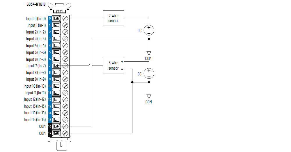
To establish more COM connections, install a 5034-MBPTM or 5034-MBPTMXT next to the
module.
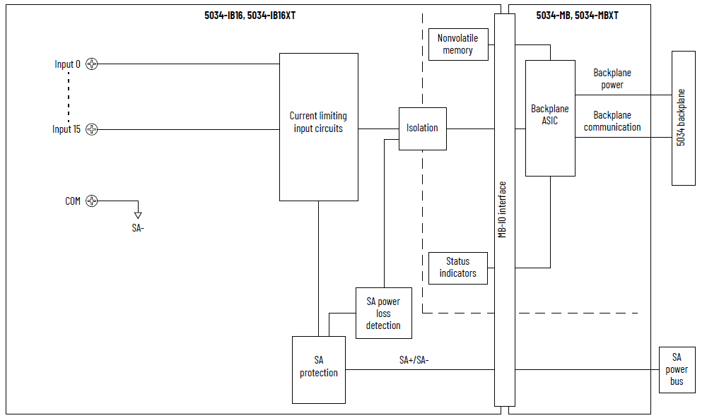
5034-IB16 and 5034-IB16XT Functional Block Diagram
Attribute | 5034-IB16, 5034-IB16XT |
|---|---|
On-state voltage range | 10…30V DC |
On-state current, min | 2 mA |
On-state current, nom | 2.4 mA |
On-state current, max | 2.8 mA |
Off-state voltage, max | 5V DC |
Off-state current, max | 1.5 mA |
Input impedance, min | 3.57 kΩ @ 10V DC |
Input impedance, nom | 10 kΩ @ 24V DC |
Input impedance, max | 15 kΩ @ 30V DC |
Input delay time (screw to backplane), max Off-to-On On-to-Off | 150 µs |
Input pulse width, min Off-to-On On-to-Off | 125 µs |
Input filter time Off-to-On On-to-Off | 0 µs, 100 µs, 200 µs, 500 µs, 1 ms (Default), 2 ms, 5 ms, 10
ms, 20 ms, 50 ms |
Simple counters, counter frequency | 0…f max = 4000 Hz4 (with 12 points as standard inputs) or 8 (with 8 points as
standard inputs) Point 0…7 only |
Timestamp of inputs (sequence of events) | Yes, ±100 µs accuracy |
Events | Not supported |
Attribute | 5034-IB16, 5034-IB16XT |
|---|---|
Number of inputs | 16 channels (1 group of 16), sinking |
Voltage category | 12/24V DC sink |
Input voltage, nom | 24V DC |
Input voltage range | 10…30V DC |
SA power voltage, nom | 24V DC |
SA power voltage range | 10…30V DC |
SA power current, nom | 20 mA |
SA power current, max | 0.1 A |
SA power current at no load | 10 mA |
SA reverse polarity protection | Yes |
Power dissipation, max (1) | 1.45 W |
Thermal dissipation, max (1) | 4.95 BTU/hr |
Isolation voltage | 250V (continuous), Basic Insulation Type, System to Field No isolation between SA power and inputs No isolation between individual inputs |
RIUP support | Yes |
CIP Sync | Yes, slave only ordinary clock |
Electronic keying | Electronic keying via programming software |
RTB key positions (slot) | 1, 4, 11 |
RTB supported | 5034-RTB18, 5034-RTB18S |
Wiring category (2) | 2 - Signal ports 2 - Power ports |
Wiring specification | See Wiring Specifications for Removable Terminal Blocks in
the PointMax I/O System Specifications Technical Data,
publication 5034-TD001 |
Indicators | 1 green/red module status indicator 1 green/red SA power status indicator 16 yellow I/O status indicators |
Dimensions (HxWxD), approx | 123.6 x 15.0 x 66.4 mm (4.87 x 0.59 x 2.61 in.) |
Weight, approx | 43.0 g (1.52 oz.) – 5034-IB16 45.0 g (1.59 oz.) – 5034-IB16XT |
Enclosure type | None (Open-style) |
North American temp code | T4 |
UKEX/ATEX temp code | T4 |
IECEx temp code | T4 |
(1) Value is measured at 60 °C (140 °F). Power dissipation
varies with temperature. (2) Use this Conductor Category information for planning
conductor routing. See the Industrial Automation Wiring and
Grounding Guidelines, publication 1770-4.1. Use this
Conductor Category information for planning conductor
routing as described in the appropriate System Level
Installation Manual. | |
Provide Feedback