Wiring Diagrams for Safety Mode and Safety Pulse Mode
The following wiring diagrams show the output modules in Safety Mode and Safety Pulse
Mode.
IMPORTANT:
The Safety level that is shown in the diagrams is applicable to the module
itself. Connected devices must have their own status monitoring to achieve
application safety level.
IMPORTANT:
You must use an SELV/PELV-listed power supply with the safety modules.
5034-OB8S and 5034-OB8SXT – SIL 2, PLc, Cat. 2 in Single-channel Safety Mode
or Safety Pulse Mode
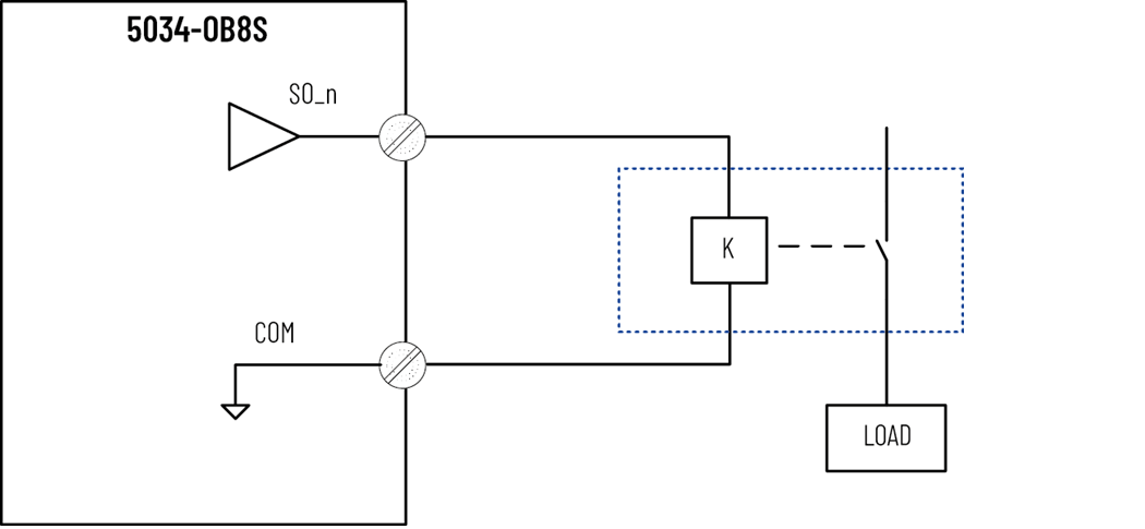
- n = 0…7
SIL Level and Category | Fault Exclusion | Other | Point Mode |
|---|---|---|---|
SIL 2, PLc, Cat. 2 | None | External connected device must be SIL 2 rated |
|
IMPORTANT:
In the event that an external wire cross-circuit occurs between the positive
potential (that is, SA+) and SO_n, the load is no longer able to shut down. The
module detects the channel fault and sets the fault bit, which indicates that
the channel cannot transition to Safe State until the fault is cleared.
5034-OB8S and 5034-OB8SXT – Up to and Including SIL 3, PLe, Cat. 4 in
Single-channel Safety Mode or Safety Pulse Mode
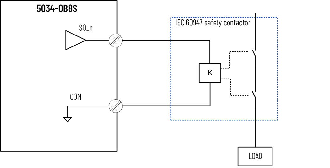
- n = 0…7
SIL Level and Category | Fault Exclusion | Other | Point Mode |
|---|---|---|---|
SIL 2, PLd, Cat. 3 | External Wiring Fault | External connected device must be SIL 2 rated |
|
SIL 3, PLe, Cat. 4 | Use IEC 60947 safety contactor |
|
5034-OB8S and 5034-OB8SXT – SIL 3, PLe, Cat. 4 in Dual-channel Safety Pulse
Mode or Safety Mode

- n = 0, 2, 4, 6
- The channel pairs that support dual-channel mode are:
- Channel 0, 1 pair
- Channel 2, 3 pair
- Channel 4, 5 pair
- Channel 6, 7 pair
SIL Level and Category | Fault Exclusion | Point Mode |
|---|---|---|
SIL 3, PLe, Cat. 4 | None | Safety Pulse Mode |
External Wiring Fault | Safety Mode Condition: You must issue at least one safety demand every 24
hours. |
Provide Feedback