5034-OB8S and 5034-OB8SXT Safety Digital 8 Output Modules
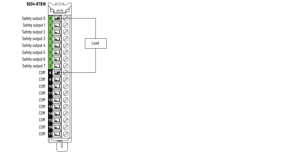
For more examples of wiring diagrams for 5034-OB8S and 5034-OB8SXT that can be used
in functional safety applications, see the PointMax Digital I/O Modules User Manual,
publication 5034-UM002. The wiring configuration
affects the safety application level to which a PointMax safety I/O module is
suitable.
5034-OB8S and 5034-OB8SXT Wiring Diagram
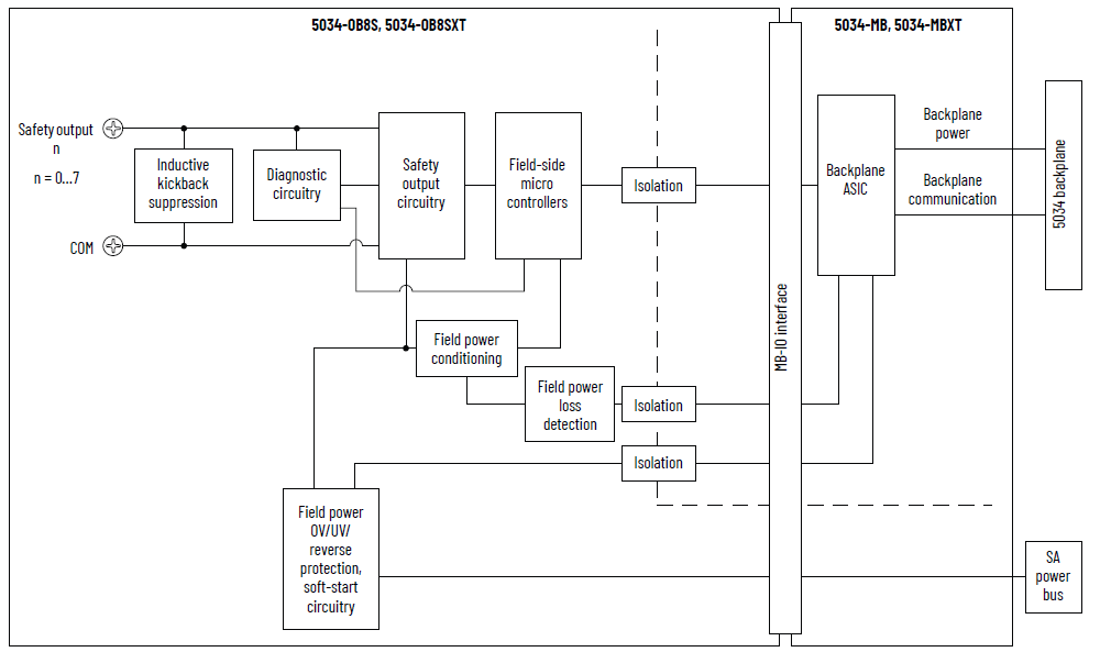
5034-OB8S and 5034-OB8SXT Functional Block Diagram
Attribute | 5034-OB8S, 5034-OB8SXT |
|---|---|
On-state voltage range | 17.5…30V DC |
On-state voltage drop, max | 0.5V DC @ 1 A |
Off-state voltage, max | 5V DC with min 10 kΩ load |
Off-state leakage current per point, max | 0.5 mA |
Output current rating per point, max | 1 A @ 40 °C (104 °F) 0.5 A @ 60 °C (140 °F) |
Output current rating per module, total | 8 A @ 40 °C (104 °F) 4 A @ 60 °C (140 °F) |
Field capacitance limit permitted per output, max | 100 nF |
Field inductance limit permitted per output, max | 1.2 H @ 0.5 A |
Output clamping voltage for inductive load when turned off,
max | 53V DC |
Surge current per point, max | 2.4 A for 50 ms, repeatable every 2 s The module current rating cannot exceed 10 A. |
Safety class (1) | Up to and including Cat. 4 / PL e acc. to EN ISO 13849-1, SIL
3 acc. to IEC 61508 |
SRT | 6 ms |
Safety Test Pulse width, max | 0.7 ms |
Safety Test Pulse period, typical | 512 ms |
Open load detection diagnostics | Off state (can be enabled manually) |
Output overload detection | Yes, 4 A typical |
Output short to high detection | Yes in Safety Pulse Test mode |
Channel-to-channel short-circuit detection | Yes in Safety Pulse Test mode |
Module over-temperature detection | Yes |
Output short to ground/overload protection | Yes |
SA supply reverse voltage protection | Yes |
SA supply overvoltage protection, max | 60V DC |
(1) See the PointMax Digital I/O Modules User Manual,
publication 5034-UM002, for
Safety Application Suitability Levels and Safety Data for
safety modules. | |
Attribute | 5034-OB8S, 5034-OB8SXT |
|---|---|
Outputs per module | 8 |
Output type | Sourcing |
SA power nominal operating supply voltage | 24V DC |
SA power operating voltage range | 18…30V DC |
SA power current, nom | 8.1 A @ 40 °C (104 °F) 4.1 A @ 60 °C (140 °F) |
SA power current, max | 8.1 A @ 40 °C (104 °F) 4.1 A @ 60 °C (140 °F) |
SA power current at no load | 20 mA @ 24V DC |
Power dissipation, max | 2.6 W @ 40 °C (104 °F) 1.4 W @ 60 °C (140 °F) |
Thermal dissipation, max | 8.87 BTU/hr @ 40 °C (104 °F) 4.78 BTU/hr @ 60 °C (140 °F) |
Isolation voltage | 250V (continuous), Basic Insulation Type, System to Field No isolation between SA power and output ports No isolation between individual output ports |
RIUP support | Yes |
CIP Sync | Yes, slave only ordinary clock |
Electronic keying | Electronic keying via programming software |
RTB key positions (slot) | 1, 5, 14 |
RTB supported | 5034-RTB18, 5034-RTB18S |
Wiring category (1) | 2 - Signal ports 2 - Power ports |
Wiring specification | See Wiring Specifications for Removable Terminal Blocks in
the PointMax I/O System Specifications Technical Data,
publication 5034-TD001 |
Indicators | 1 green/red module status indicator 1 green/red SA power status indicator 8 yellow/red I/O status indicators |
Dimensions (HxWxD), approx | 123.6 x 15.0 x 66.4 mm (4.87 x 0.59 x 2.61 in.) |
Weight, approx | 46.0 g (1.62 oz.) – 5034-OB8S 49.0 g (1.73 oz.) – 5034-OB8SXT |
Enclosure type | None (Open-style) |
North American temp code | T4 |
UKEX/ATEX temp code | T4 |
IECEx temp code | T4 |
(1) Use this Conductor Category information for planning
conductor routing. See the Industrial Automation Wiring and
Grounding Guidelines, publication 1770-4.1. Use this
Conductor Category information for planning conductor
routing as described in the appropriate System Level
Installation Manual. | |
Provide Feedback