Wiring Diagrams for Safety Mode and Safety Pulse Mode
The following wiring diagrams show the input modules in Safety Mode and Safety Pulse
Mode.
A Test Output (TO) can be associated to any Safety Input (SI). One TO can only be wired
to a maximum of four SI.
In Safety Pulse Mode, if the external wiring shorts two SI from the same TO point, the
short circuit is not detectable.Therefore, connect two SI from different TO points when
in Safety Pulse Mode.
IMPORTANT:
You must use an SELV/PELV-listed power supply with the safety modules.
5034-IB8S and 5034-IB8SXT – SIL 2, PLc, Cat. 2 in Single-channel Safety Pulse
Mode
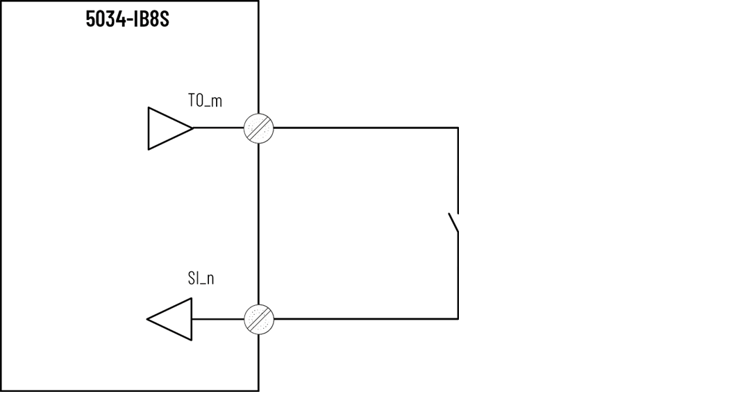
- SI_n (n = 0…7)
- TO_m (m = 0…3)
- TO configured to pulse test mode
SIL Level and Category | Fault Exclusion | Other | Point Mode |
|---|---|---|---|
SIL 2, PLc, Cat. 2 | None | External connected device must be SIL 2 rated | Safety Pulse Mode |
5034-IB8S and 5034-IB8SXT – SIL 2, PLc, Cat. 2 in Single-channel Safety
Mode
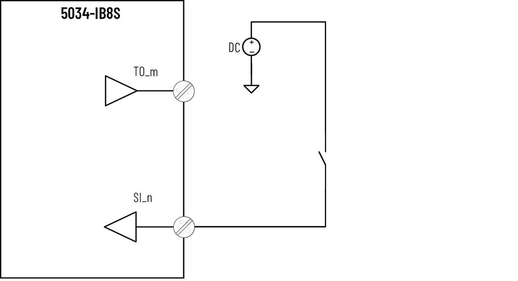
- SI_n (n = 0…7)
- TO_m (m = 0…3)
- Any TO in power supply mode or external power supply can be used
SIL Level and Category | Fault Exclusion | Other | Point Mode |
|---|---|---|---|
SIL 2, PLc, Cat. 2 | None | External connected device must be SIL 2 rated | Safety Mode |
5034-IB8S and 5034-IB8SXT – SIL 3, PLe, Cat. 4 in Single-channel Safety Pulse
Mode
- SI_n (n = 0…7)
- TO_m (m = 0…3)
- TO configured to pulse test mode
SIL Level and Category | Fault Exclusion | Other | Point Mode |
|---|---|---|---|
SIL 3, PLe, Cat. 4 | External Wiring Fault | Use SIL 3, PLe, Cat. 4 qualified sensor | Safety Pulse Mode |
5034-IB8S and 5034-IB8SXT – SIL 3, PLe, Cat. 4 in Single-channel Safety
Mode
- SI_n (n = 0…7)
- TO_m (m = 0…3)
- Any TO in power supply mode or external power supply can be used
SIL Level and Category | Fault Exclusion | Other | Point Mode |
|---|---|---|---|
SIL 3, PLe, Cat. 4 | External Wiring Fault | Use SIL 3, PLe, Cat. 4 qualified sensor | Safety Mode |
5034-IB8S and 5034-IB8SXT – SIL 3, PLe, Cat. 4 in Safety Pulse Mode Using 2
Single-channel
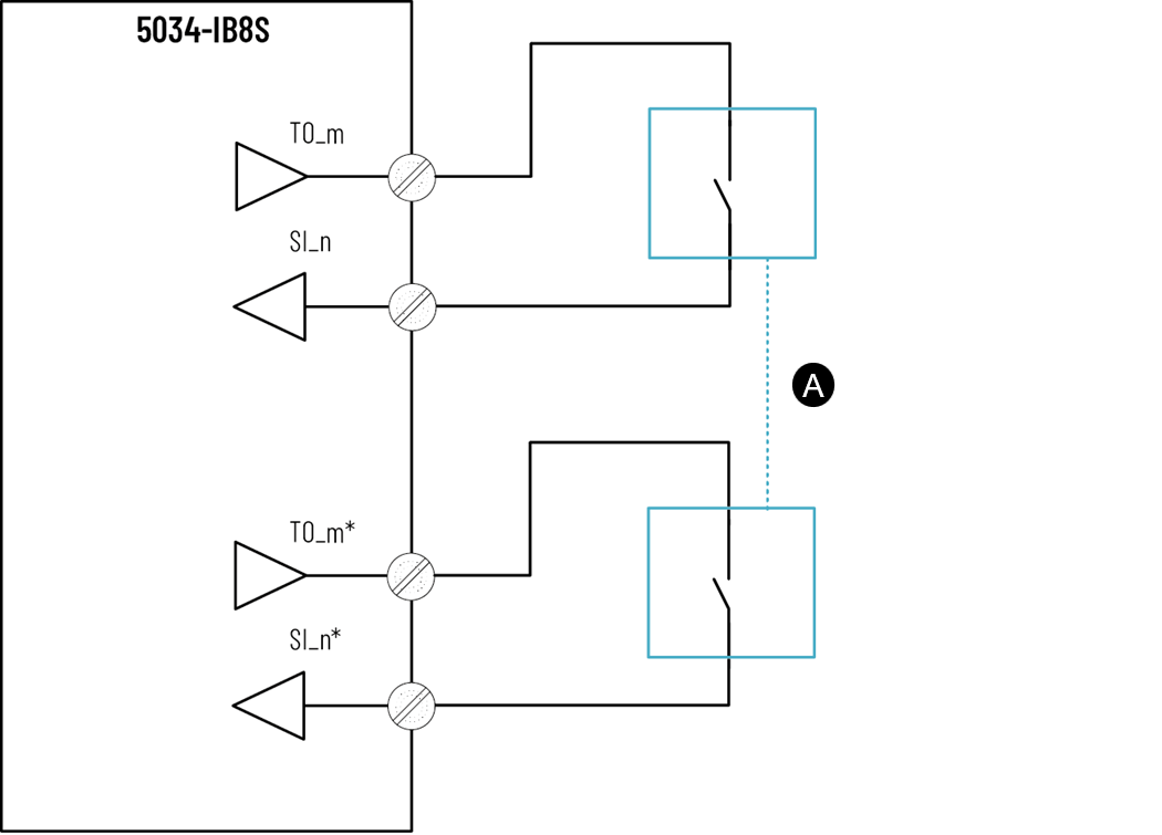
- A = Two single-channel sensors sensing same process value
- SI_n (n = 0…7)
- TO_m (m = 0…3)
- n ≠ n*
- m ≠ m*
- TO configured to pulse test mode
SIL Level and Category | Fault Exclusion | Point Mode |
|---|---|---|
SIL 3, PLe, Cat. 4 | None | Safety Pulse Mode |
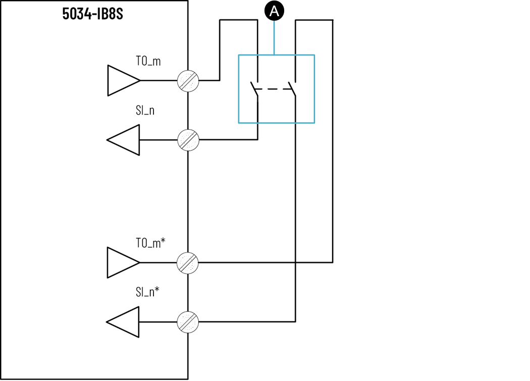
5034-IB8S and 5034-IB8SXT – SIL 3, PLe, Cat. 4 in Safety Mode Using 2
Single-channel
- A = Two single-channel sensors sensing same process value
- SI_n (n = 0…7)
- TO_m (m = 0…3)
- n ≠ n*
- Any TO in power supply mode or external power supply can be used
SIL Level and Category | Fault Exclusion | Point Mode |
|---|---|---|
SIL 3, PLe, Cat. 4 | External Wiring Fault | Safety Mode |
5034-IB8S and 5034-IB8SXT – SIL 3, PLe, Cat. 4 in Safety Pulse Mode Using 2
Single-channel
- A = Equivalent sensor
- SI_n (n = 0…7)
- TO_m (m = 0…3)
- n ≠ n*
- m ≠ m*
- TO configured to pulse test mode
SIL Level and Category | Fault Exclusion | Point Mode |
|---|---|---|
SIL 3, PLe, Cat. 4 | None | Safety Pulse Mode |
5034-IB8S and 5034-IB8SXT – SIL 3, PLe, Cat. 4 in Safety Mode Using 2
Single-channel
- A = Equivalent sensor
- SI_n (n = 0…7)
- TO_m (m = 0…3)
- n ≠ n*
- Any TO in power supply mode or external power supply can be used
SIL Level and Category | Fault Exclusion | Point Mode |
|---|---|---|
SIL 3, PLe, Cat. 4 | External Wiring Fault | Safety Mode |
5034-IB8S and 5034-IB8SXT – SIL 3, PLe, Cat. 4 in Safety Pulse Mode Using 2
Single-channel
- A = Non-equivalent sensor
- SI_n (n = 0…7)
- TO_m (m = 0…3)
- n ≠ n*
- m ≠ m*
- TO configured to pulse test mode
SIL Level and Category | Fault Exclusion | Point Mode |
|---|---|---|
SIL 3, PLe, Cat. 4 | None | Safety Pulse Mode |
5034-IB8S and 5034-IB8SXT – SIL 3, PLe, Cat. 4 in Safety Mode using 2
Single-channel
- A = Non-equivalent sensor
- SI_n (n = 0…7)
- TO_m (m = 0…3)
- n ≠ n*
- Any TO in power supply mode or external power supply can be used
SIL Level and Category | Fault Exclusion | Point Mode |
|---|---|---|
SIL 3, PLe, Cat. 4 | External Wiring Fault | Safety Mode |
Provide Feedback