5034-OF4 and 5034-OF4XT Analog 4 Output Modules
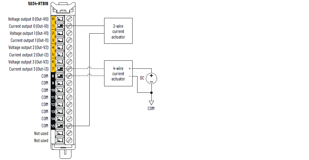
5034-OF4 and 5034-OF4XT Wiring Diagram – Current Mode
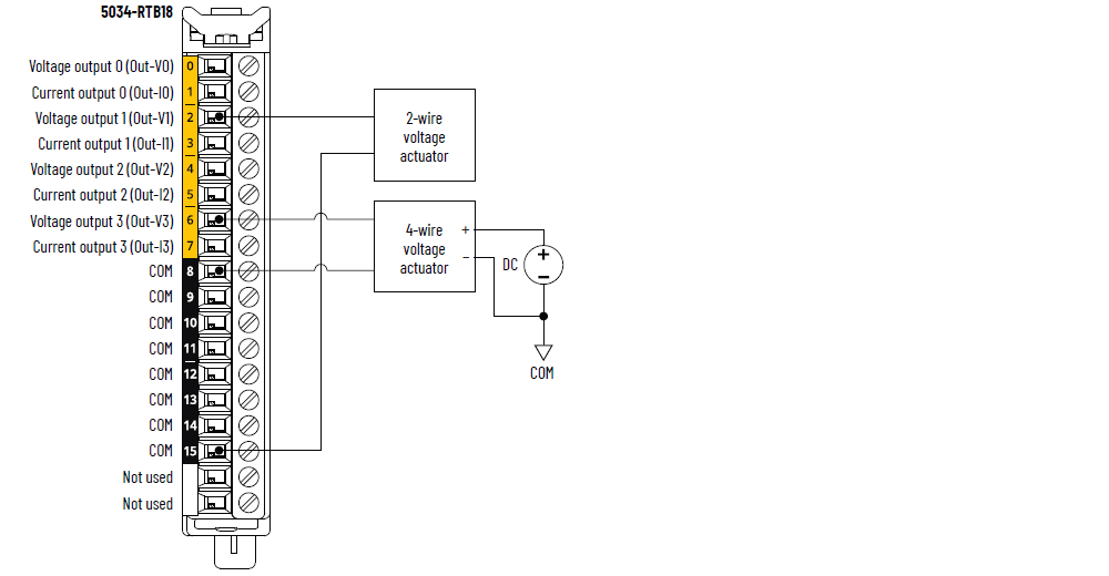
5034-OF4 and 5034-OF4XT Wiring Diagram – Voltage Mode
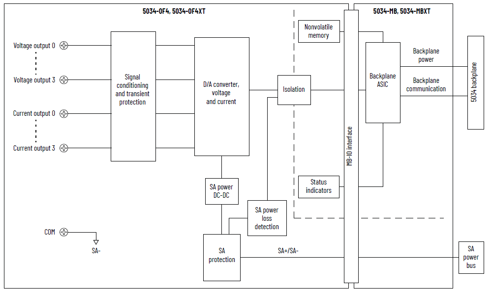
5034-OF4 and 5034-OF4XT Functional Block Diagram
Attribute | 5034-OF4, 5034-OF4XT |
|---|---|
Output range, voltage | ±10V 0…10V 0…5V |
Output range, current | 0…20 mA 4…20 mA |
Resolution, voltage | ±10V: 15 bits 0…10V: 16 bits 0…5V: 16 bits |
Resolution, current | 16 bits |
Calibrated accuracy at 25 °C (77 °F) | Voltage: 0.10% full scale Current: 0.10% full scale |
Calibrated accuracy over full temperature range -25…+60 °C (-13…+140 °F) | Voltage: 0.2% full scale Current: 0.2% full scale |
Drive capability | Voltage: 3000 Ω min Current: 500 Ω max |
Capacitive load, max (voltage mode only) | 1 µF |
Inductive load, max (current mode only) | 1 mH |
HART handheld compliance | Yes |
Open wire detection | Current mode only |
Short circuit detection | Voltage mode only – Output electronically limited to 16 mA or
less |
Data format | IEEE 754 32-bit floating point |
Module conversion method | DAC |
Update rate | 1 channel: 0.2 ms All channels: 0.4 ms |
Step response time to 63% of full scale per channel | Voltage mode: 0.07 ms typical Current mode: 0.4 ms typical |
Backplane to screw response time (63% of full scale) | Voltage mode 1 channel: 0.5 ms typical All channels: 1 ms typical Current mode: 1 channel: 0.9 ms typical All channels: 1.4 ms typical |
Overvoltage protection, max | 32V DC |
Attribute | 5034-OF4, 5034-OF4XT |
|---|---|
Number of outputs | 4 channels, single-ended Configurable voltage or current mode at channel level |
SA power voltage, nom | 24V DC |
SA power voltage range | 10…30V DC |
SA power current, nom | 100 mA |
SA power current, max | 0.25 A |
SA power current at no load | 40 mA |
SA reverse polarity protection | Yes |
Power dissipation, max | 0.95 W |
Thermal dissipation, max | 3.24 BTU/hr |
Isolation voltage | 250V (continuous), Basic Insulation Type, System to Field No isolation between SA power and output ports No isolation between individual output ports |
Calibration | Factory-calibrated Manual calibration supported, see PointMax Analog I/O Modules
User Manual, publication 5034-UM003 |
RIUP support | Yes |
Electronic keying | Electronic keying via programming software |
RTB key positions (slot) | 2, 5, 10 |
RTB supported | 5034-RTB18, 5034-RTB18S |
Wiring category (1) | 2 - Signal ports 2 - Power ports |
Wiring specification | See Wiring Specifications for Removable Terminal Blocks in
the PointMax I/O System Specifications Technical Data,
publication 5034-TD001 |
Indicators | 1 green/red module status indicator 1 green/red SA power status indicator 4 yellow/red I/O status indicators |
Dimensions (HxWxD), approx | 123.6 x 15.0 x 66.4 mm (4.87 x 0.59 x 2.61 in.) |
Weight, approx | 47.0 g (1.66 oz.) – 5034-OF4 49.0 g (1.73 oz.) – 5034-OF4XT |
Enclosure type | None (Open-style) |
North American temp code | T4 |
UKEX/ATEX temp code | T4 |
IECEx temp code | T4 |
(1) Use this Conductor Category information for planning
conductor routing. See the Industrial Automation Wiring and
Grounding Guidelines, publication 1770-4.1. Use this
Conductor Category information for planning conductor
routing as described in the appropriate System Level
Installation Manual. | |
Provide Feedback