5034-IRT4I and 5034-IRT4IXT Analog 4 Input Isolated RTD/TC Modules
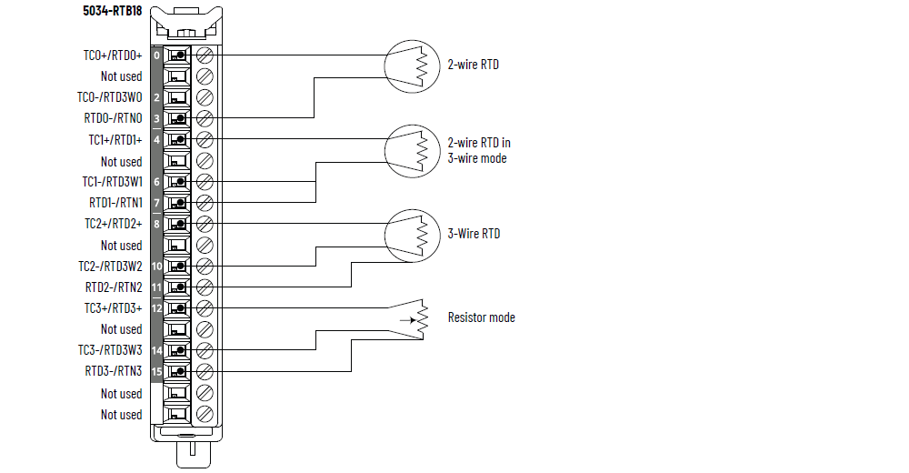
5034-IRT4I and 5034-IRT4IXT Wiring Diagram – RTD Mode
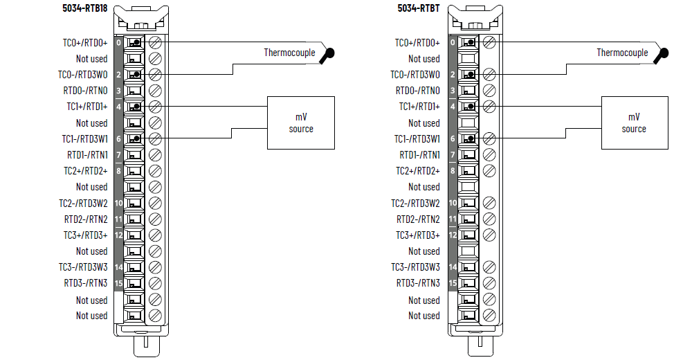
5034-IRT4I and 5034-IRT4IXT Wiring Diagram – Thermocouple Mode
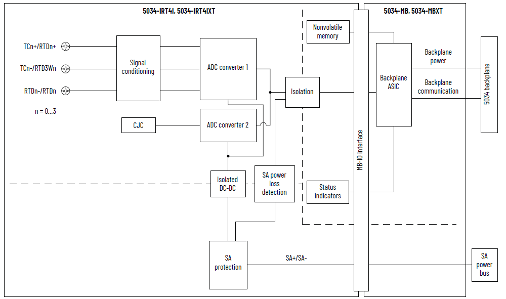
5034-IRT4I and 5034-IRT4IXT Functional Block Diagram
Attribute | 5034-IRT4I, 5034-IRT4IXT |
|---|---|
Input range, resistive | 1…500 Ω 2…1000 Ω 4…2000 Ω 8…4000 Ω |
Input type, RTD | 100, 200, 500, 1000 Ω platinum, alpha = 385 100, 200, 500, 1000 Ω platinum, alpha = 3916 120 Ω nickel, alpha = 672 100, 120, 200, 500 Ω nickel, alpha = 618 10 Ω copper 427 |
Input range, thermocouple/millivolt | ±100 mV |
Input type, thermocouple | B, C, D, E, J, K, N, R, S, T, TXK/XK(L) |
Input impedance | Thermocouple/millivolt: > 1 MΩ RTD: > 1 MΩ |
Common mode voltage (channel to channel) | 250V (continuous), Basic Isolation |
Module conversion method | Sigma-delta, 24-bit multiplexed ADC |
Resolution, RTD/resistive At 50/60 Hz notch filter | 16 bit |
Resolution, thermocouple/millivolt At 50/60 Hz notch filter | 16 bit |
RTD excitation current | 250 µA for 1000, 2000, 4000 Ω range 500 µA for 500 Ω range |
Thermocouple linearization | ITS-90 |
CJ mode | Onboard CJC, RTB CJC, remote CJC |
Onboard CJC inputs (for thermocouple mode use only) | CJC sensors Four thermistors embedded in 5034-IRT4I and 5034-IRT4IXT Vishay NTCS0805E3103FHT |
Onboard CJC sensor accuracy | ±3.0 °C, 0 °C < T amb < 60 °C (±5.4 °F, 32 °F
< Tamb < 140 °F)±4.0 °C, -25 °C < T amb < 0 °C (±7.2 °F, -13
°F < Tamb < 32 °F) |
RTB CJC inputs (for thermocouple mode use only) | CJC sensors Four thermistors embedded in 5034-RTBT and 5034-RTBTS TE Connectivity TE 10K3A1A |
RTB CJC sensor accuracy | ±0.6 °C, 0 °C < T amb < 60 °C (±1.1 °F, 32 °F
< Tamb < 140 °F)±1.2 °C, -25 °C < T amb < 0 °C (±2.2 °F, -13
°F < Tamb < 32 °F) |
CJC conversion method | 12-bit SAR |
Calibrated accuracy at 25 °C (77 °F) | Thermocouple/millivolt: 0.1% full scale with 50/60 Hz
filter RTD: 500 Ω, 1 kΩ, 2 kΩ, 4 kΩ range, 0.1% full scale with
50/60 Hz filter |
Calibrated accuracy over full temperature range -25…+60 °C (-13…+140 °F) | Thermocouple/millivolt: 0.25% full scale with 50/60 Hz
filter RTD: 500 Ω, 1 kΩ, 2 kΩ, 4 kΩ range, 0.25% full scale with
50/60 Hz filter |
Fastest scan time per channel | 0.36 ms |
Fastest scan time per module | 0.36 ms |
Input notch filter selections (Hz) | 10, 20, 50, 60 (Default), 100, 200, 500, 1000, 2500, 5000 |
Hardware input filter | 1 kHz |
Input digital filter | First order lag, 0 ms (Default) 0…32,767 ms (32.767 s) |
Normal mode noise rejection ratio | 65 dB @ 50/60 Hz, notch filter dependent |
Open wire detection time | < 200 ms |
Overvoltage protection, max | 32V DC |
Scaling to engineering units | Yes |
Real-time channel sampling | Yes |
Rolling timestamp of inputs | Yes |
Data format | IEEE 754 32-bit floating point |
RTD Sensor Types (1) | Temperature Range |
|---|---|
100, 200, 500, 1000 Ω PT 385 | -200…+870 °C -328…+1598 °F 73…1143 K 132…2058 °R |
100, 200, 500, 1000 Ω PT 3916 | -200…+630 °C -328…+1166 °F 73…903 K 132…1626 °R |
10 Ω CU 427 | -200…+260 °C -328…+500 °F 73…533 K 132…960 °R |
120 Ω NI 672 | -80…+320 °C -112…+608 °F 193…593 K 348…1068 °R |
100, 120, 200, 500 Ω NI 618 | -60…+250 °C -76…+482 °F 213…523 K 384…942 °R |
(1) Each sensor type supports all temperature ranges
listed. | |
Thermocouple Type | Temperature Range |
|---|---|
Thermocouple type B | 21…1820 °C 68…3308 °F 293…2093 K 528…3768 °R |
Thermocouple type C | 0…2315 °C 32…4199 °F 273…2588 K 492…4659 °R |
Thermocouple type D | 0…2315 °C 32…4199 °F 273…2588 K 492…4659 °R |
Thermocouple type E | -270…+1000 °C -454…+1832 °F 3…1273 K 6…2292 °R |
Thermocouple type J | -210…+1200 °C -346…+2192 °F 63…1473 K 114…2652 °R |
Thermocouple type K | -270…+1372 °C -454…+2502 °F 3…1645 K 6…2961 °R |
Thermocouple type N | -270…+1300 °C -454…+2372 °F 3…1573 K 6…2832 °R |
Thermocouple type R | -50…+1768 °C -58…+3215 °F 223…2041 K 402…3674 °R |
Thermocouple type S | -50…+1768 °C -58…+3215 °F 223…2041 K 402…3674 °R |
Thermocouple type T | -270…+400 °C -454…+752 °F 3…673 K 6…1212 °R |
Thermocouple type TXK/XK(L) | -200…+800 °C -328…+1472 °F 73…1073 K 132…1932 °R |
Attribute | 5034-IRT4I, 5034-IRT4IXT |
|---|---|
Number of inputs | 4 channels (4 isolated group) |
SA power voltage, nom | 24V DC |
SA power voltage range | 10…30V DC |
SA power current, nom | 50 mA |
SA power current, max | 0.1 A |
SA power current at no load | 11 mA |
SA reverse polarity protection | Yes |
Power dissipation, max (1) | 0.42 W |
Thermal dissipation, max (1) | 1.43 BTU/hr |
Isolation voltage | 250V (continuous), Basic Insulation Type, System to Field 250V (continuous), Basic Insulation Type, SA power and input
ports 250V (continuous), Basic Insulation Type, between individual
input ports |
Calibration | Factory-calibrated Manual calibration supported, see PointMax Analog I/O Modules
User Manual, publication 5034-UM003 |
RIUP support | Yes |
CIP Sync | Yes, slave only ordinary clock |
Electronic keying | Electronic keying via programming software |
RTB key positions (slot) | 2, 7, 10 |
RTB supported | 5034-RTB18, 5034-RTB18S, 5034-RTBT, 5034-RTBTS To help achieve better accuracy, use the CJC thermistors that
are embedded in 5034-RTBT and 5034-RTBTS. |
Wiring category (2) | 2 - Signal ports 2 - Power ports |
Wiring specification | See Wiring Specifications for Removable Terminal Blocks in
the PointMax I/O System Specifications Technical Data,
publication 5034-TD001 |
Indicators | 1 green/red module status indicator 1 green/red SA power status indicator 4 yellow/red I/O status indicators |
Dimensions (HxWxD), approx | 123.6 x 15.0 x 66.4 mm (4.87 x 0.59 x 2.61 in.) |
Weight, approx | 45.0 g (1.59 oz.) – 5034-IRT4I 48.0 g (1.69 oz.) – 5034-IRT4IXT |
Enclosure type | None (Open-style) |
North American temp code | T4 |
UKEX/ATEX temp code | T4 |
IECEx temp code | T4 |
(1) Value is measured at 60 °C (140 °F). Power dissipation
varies with temperature. (2) Use this Conductor Category information for planning
conductor routing. See the Industrial Automation Wiring and
Grounding Guidelines, publication 1770-4.1. Use this
Conductor Category information for planning conductor
routing as described in the appropriate System Level
Installation Manual. | |
Provide Feedback