Calibration Procedure
This procedure describes how to calibrate a channel on the analog input module for use with
a Current (mA) input type. You can follow the same procedure for voltage input type, but
make sure connect the voltage calibrator to the channel.
Apply Low and High Signal references to the analog input module to calibrate it. The
references must match the input range the channel is using.
Input Type | Input Range | Low Calibration Reference | High Calibration Reference |
|---|---|---|---|
Voltage (V) | -10…10V | 0.0V | 10.0V |
0…10V | 0.5V | 10.0V | |
0…5V | 0.5V | 5.0V | |
Current (mA) | 0…20 mA 4…20 mA | 4.0 mA | 20.0 mA |
- Connect the current calibrator to the channel being calibrated.
- Go online with the project and make sure that the controller is in Program Mode.
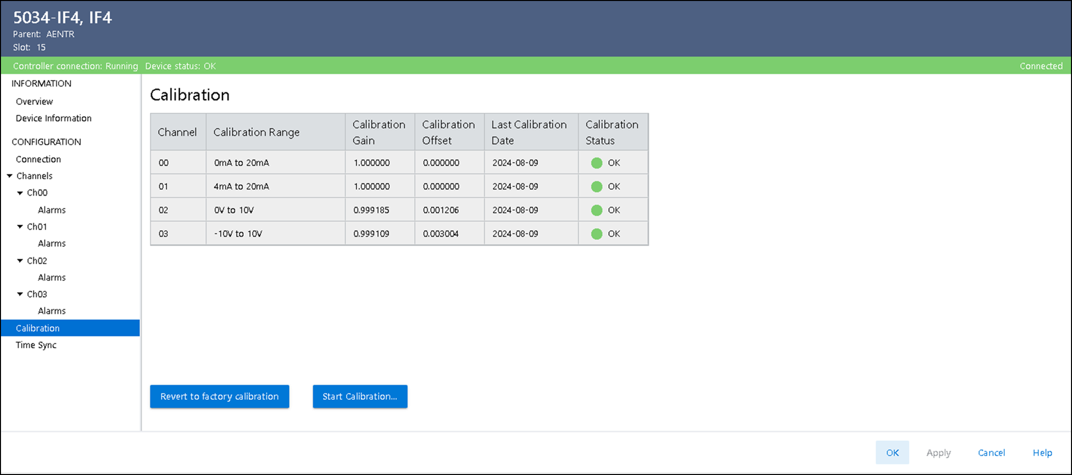
- Confirm that the channel to be calibrated is configured for the correct Input Range.
- On the Calibration view in the Module Properties dialog, select Start Calibration.
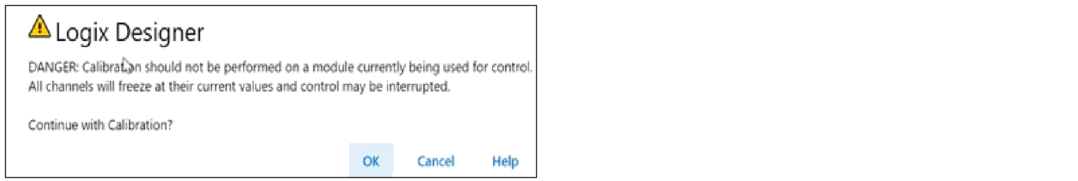
- When the dialog appears to confirm that you want to calibrate the channel, select OK.
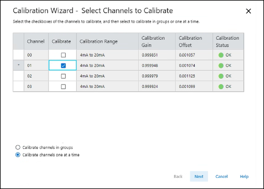
- Select the channels one at a time or in groups to calibrate and then select Next.
- When the Attach Low Reference dialog appears, set the calibrator to the low reference and apply it to the channel.
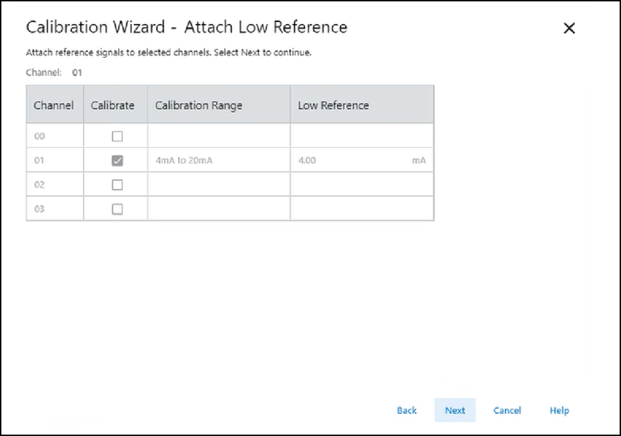
- Select Next. The Low Reference Results dialog appears and indicates the status of the calibrated channel.
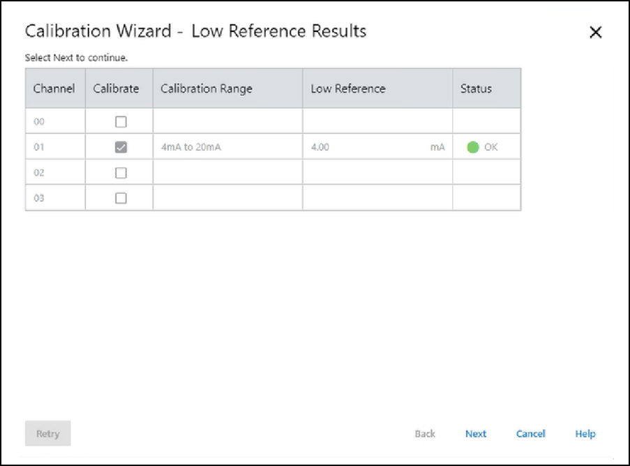
- If the Status is OK, select Next. If the Status is not OK, repeat the calibration process.
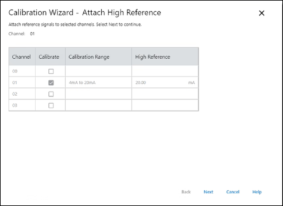
- When the Attach High Reference dialog appears, set the calibrator to the high reference and apply it to the channel.
- Select Next. The High Reference Results dialog appears and indicates the status of the calibrated channel.
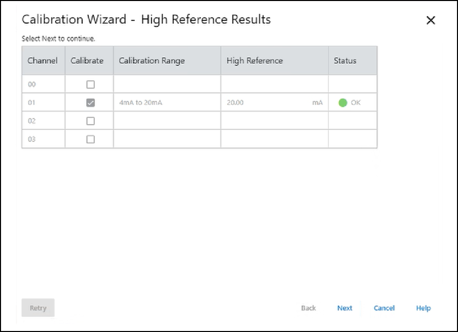
- If the Status is OK, select Next. If the Status is not OK, repeat the calibration process.
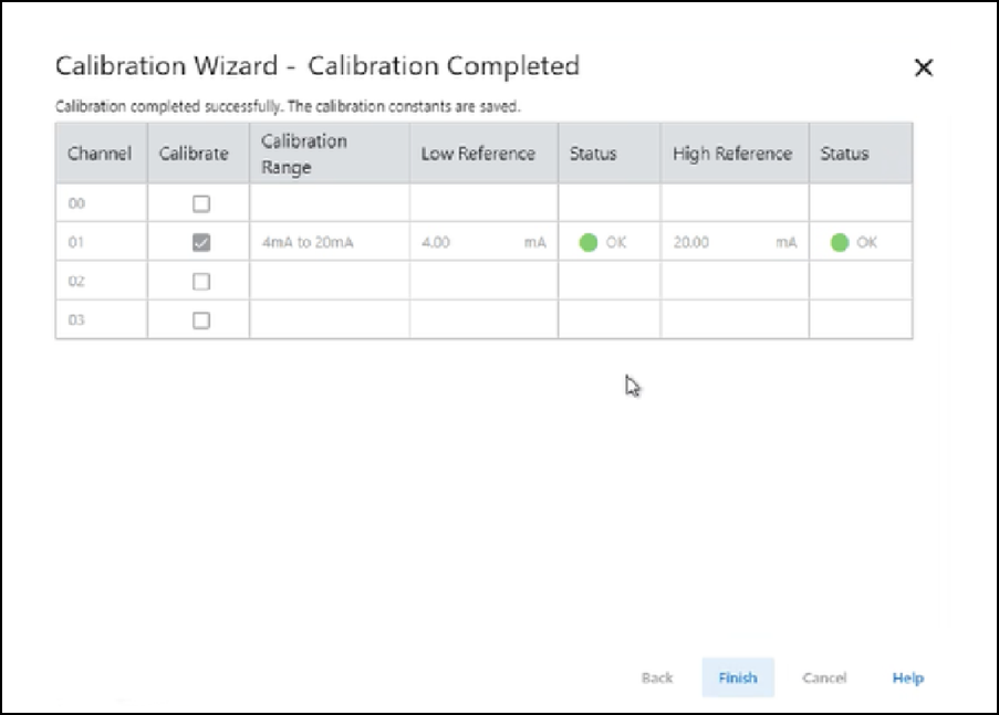
- When the Calibration Completed dialog appears, select Finish.
Provide Feedback