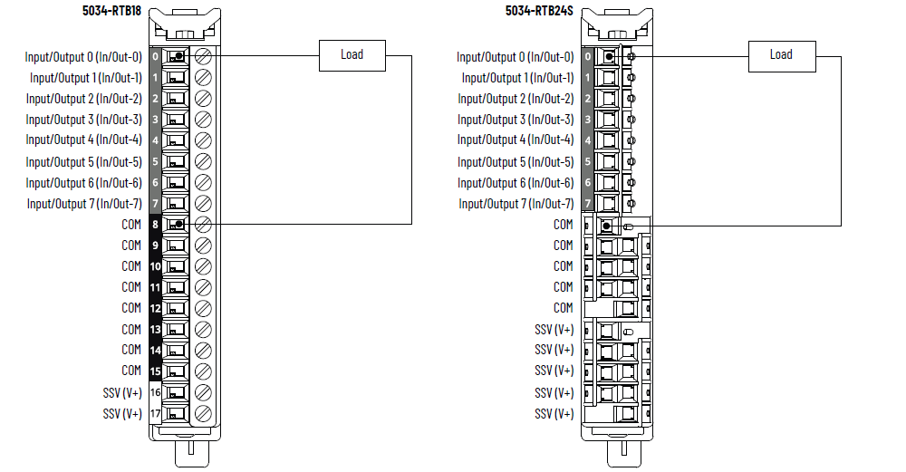
5034-UB8F and 5034-UB8FXT Fast Digital 8 Input/Output Modules
5034-UB8F and 5034-UB8FXT Wiring Diagram – Output Mode
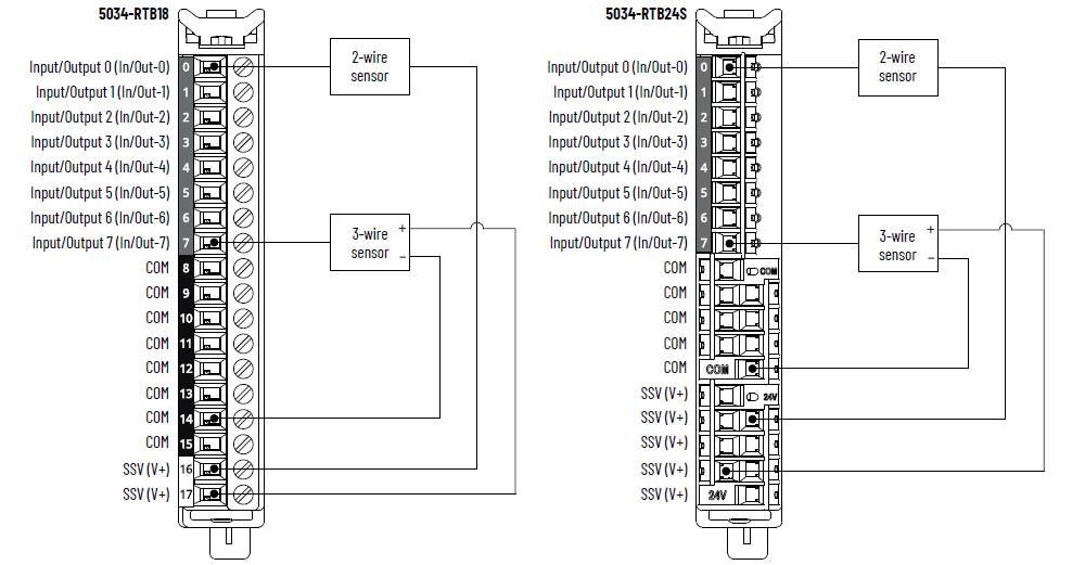
5034-UB8F and 5034-UB8FXT Wiring Diagram – Input Mode
To establish more COM/V+ connections, especially in a mixed input/output
configuration, use a 5034-RTB24S, or install a 5034-MBPTM or 5034-MBPTMXT next to
the module.
Use SSV (V+) only for powering sensors that are interfaced with a point that is
configured as a digital input mode.
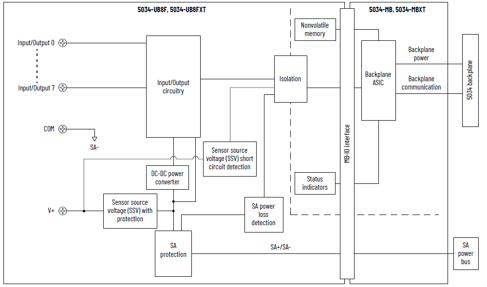
5034-UB8F and 5034-UB8FXT Functional Block Diagram
Attribute | 5034-UB8F, 5034-UB8FXT |
|---|---|
On-state voltage range | 10…30V DC |
On-state current, min | 2 mA |
On-state current, nom | 4.5 mA |
On-state current, max | 5 mA |
Off-state voltage, max | 5V DC |
Off-state current, max | 1.5 mA |
Input impedance, min | 2 kΩ @ 10V DC |
Input impedance, nom | 5.3 kΩ @ 24V DC |
Input impedance, max | 15 kΩ @ 30V DC |
Input delay time (screw to backplane), max Off-to-On On-to-Off | 40 µs |
Input pulse width, min Off-to-On On-to-Off | 10 µs |
Input filter time Off-to-On On-to-Off | 0 µs (Default), 5 µs, 10 µs, 20 µs, 50 µs, 100 µs, 200 µs,
500 µs, 1 ms, 2 ms, 5 ms, 10 ms, 20 ms, 50 ms |
Simple counters, counter frequency | 0…f max = 50,000 Hz |
Timestamp of inputs (sequence of events) | Yes, ±10 µs accuracy |
Events | Yes |
Attribute | 5034-UB8F, 5034-UB8FXT |
|---|---|
On-state voltage range | 10…30V DC |
On-state voltage drop, max | 0.25V DC |
On-state current per point, min | 1.0 mA |
Off-state voltage, max | 5V DC with 1 mA min load |
Off-state leakage current per point, max (1) | 0.5 mA |
Output current rating per point, max | 0.5 A |
Output current rating per module, max | 4 A |
Surge current per point, max | 1.2 A for 10 ms, repeatable every 3 s |
Inductive load allowed, max | 1.2 H |
Output clamping voltage for inductive load when turn off | (SA voltage + VCL)…0 VCL value: Minimum is -63V, Typical is -55V, Maximum is
-49V For more information, see the PointMax Digital I/O Modules
User Manual, publication 5034-UM002. |
Output delay time (backplane to screw), max Off-to-On On-to-Off | 20 µs @ 0.5 A |
Pulse width, min | 20 µs |
Scheduled outputs | Supported, accuracy ±10 µs |
PWM/PTO support | Yes Maximum switching frequency: 100 kHz (10 µs period) Minimum switching frequency: 0.033 Hz (30 s period) Minimum pulse width: 5 µs Maximum load current (resistive type) per point:
Where F sw is the switching frequency |
Open load detection diagnostics | Not supported |
Output short circuit/overload detection | Yes |
Output short circuit/overload protection | Yes |
Pilot duty rating | 1.2 A inrush current, 0.5 A rated current, DC-14 |
Output states in program mode per point | Hold Last State On Off (Default) Local Control |
Output states in fault mode per point | Hold Last State On Off (Default) Local Control |
Duration of fault mode per point | 1 s 2 s 5 s 10 s Forever (Default) |
Output final state after fault mode per point | On Off (Default) |
(1) Recommended Loading Resistor - To limit the effects of
leakage current through solid-state outputs, you can connect
a loading resistor in parallel with your load. For 24V DC
operation, use a 5.6 kΩ, 0.5 W resistor for transistor
operation. | |
Attribute | 5034-UB8F, 5034-UB8FXT |
|---|---|
Number of inputs/outputs | 8 channels, configurable, sinking input, sourcing output |
SA power voltage, nom | 24V DC |
SA power voltage range | 10…30V DC |
SA power current, nom | 4.1 A |
SA power current, max | 4.2 A |
SA power current at no load | 14.3 mA |
SA reverse polarity protection | Yes |
SSV voltage range | Follow SA supply |
SSV current, max | 0.8 A |
SSV short-circuit detection | Yes |
Power dissipation, max (1) | 1.43 W |
Thermal dissipation, max (1) | 4.87 BTU/hr |
Isolation voltage | 250V (continuous), Basic Insulation Type, System to Field No isolation between SA power and input/output ports No isolation between individual input/output ports |
RIUP support | Yes |
CIP Sync | Slave only ordinary clock |
Electronic keying | Electronic keying via programming software |
RTB key positions (slot) | 1, 5, 8 |
RTB supported | 5034-RTB18, 5034-RTB18S, 5034-RTB24S |
Wiring category (2) | 2 - Signal ports 2 - Power ports |
Wiring specification | See Wiring Specifications for Removable Terminal Blocks in
the PointMax I/O System Specifications Technical Data,
publication 5034-TD001 |
Indicators | 1 green/red module status indicator 1 green/red SA power status indicator 8 yellow/red I/O status indicators |
Dimensions (HxWxD), approx | 123.6 x 15.0 x 66.4 mm (4.87 x 0.59 x 2.61 in.) |
Weight, approx | 45.0 g (1.59 oz.) – 5034-UB8F 47.0 g (1.66 oz.) – 5034-UB8FXT |
Enclosure type | None (Open-style) |
North American temp code | T4 |
UKEX/ATEX temp code | T4 |
IECEx temp code | T4 |
(1) Value is measured at 60 °C (140 °F). Power dissipation
varies with temperature. (2) Use this Conductor Category information for planning
conductor routing. See the Industrial Automation Wiring and
Grounding Guidelines, publication 1770-4.1. Use this
Conductor Category information for planning conductor
routing as described in the appropriate System Level
Installation Manual. | |
Provide Feedback