Overview View
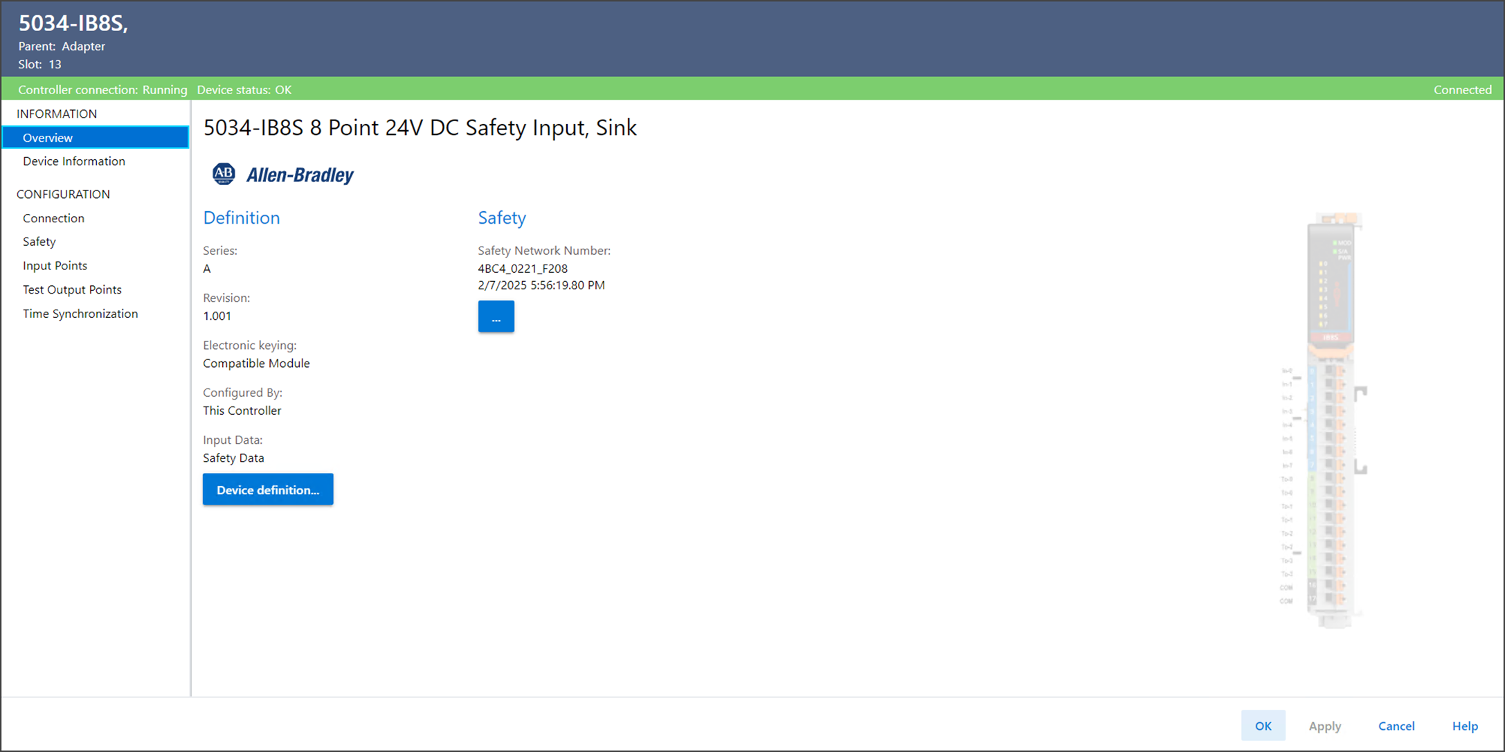
Use Overview to view the definition of a device, including the device
type, revision, electronic keying, connection, and other device-specific values.
Overview View Example
Device Definition
To change the definition of a device, select Device definition in the
Overview view.
Device Definition Example
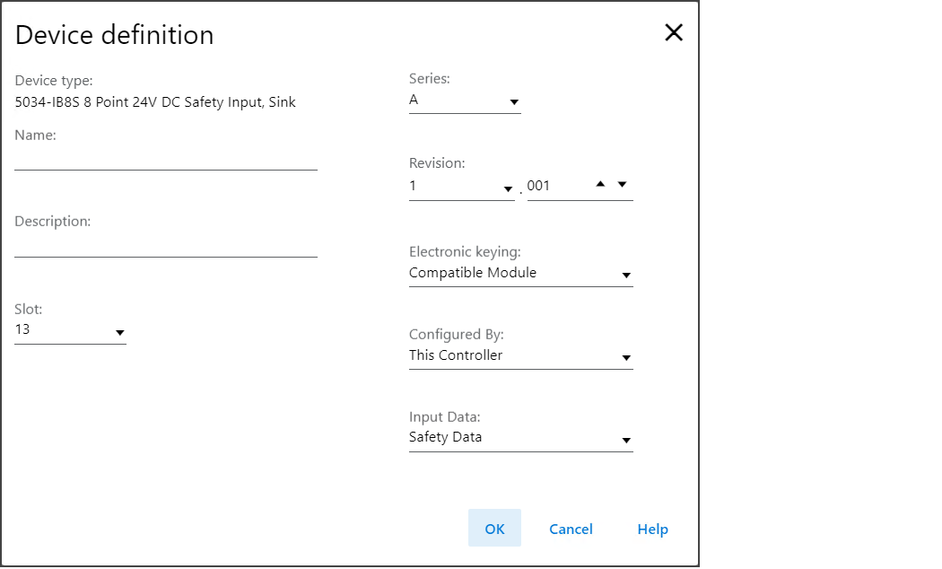
Device Definition includes these parameters:
Parameter | Definition | Available Choices |
|---|---|---|
Device Type | Displays the device catalog number and type. | Device-specific |
Name | Enter an IEC 61131 compliant device name. If an invalid character is entered in this field, or if the name exceeds 40 characters, the software ignores the character. | All valid values |
Description | Enter the description of the device. | All valid values |
Slot | Specify the slot number where the device resides. Only slots between 1 and the maximum number of I/O devices are valid depending on the platform. When the device is created, the slot number defaults to the first available slot position. When the controller is changed to one supporting a smaller maximum I/O count, the current slot value may no longer be valid. | 1…32 |
Series | Specifies the series of the device. | Device-specific |
Revision | Specifies the major and minor revisions of the device. The valid range for minor revision is from 1…255. | Device-specific |
Electronic Keying | Defines the electronic keying used for the device. Electronic
keying compares the device defined in the project to the
installed device. If keying fails, a fault occurs. For detailed information on Electronic keying, see Electronic
Keying in Logix 5000 Control Systems Application Technique,
publication LOGIX-AT001. |
|
Configured By | Determines which tags are generated when configuration is
complete. For the External Means choice, the controller and module
establish communication without the controller sending any
configuration or output data to the module. |
|
Input Data | Select the input data type for the device. |
|
Safety Network Number
The Studio 5000 Logix Designer application automatically assigns a Safety Network
Number (SNN) to safety modules as they are added to the project.
The SNN is a time-based number that uniquely identifies subnets across all networks
in the safety system. All safety modules in a same system use the same SNN and are
automatically assigned the same SNN by default.
The Studio 5000 Logix Designer application assigns an SNN to the first safety module
that is added to a remote system. The application assigns the same SNN to additional
safety modules that are added to this remote I/O system.
For more information on Safety Network Numbers, see the GuardLogix 5580 and Compact
GuardLogix 5380 Controllers Safety Reference Manual, publication 1756-RM012.
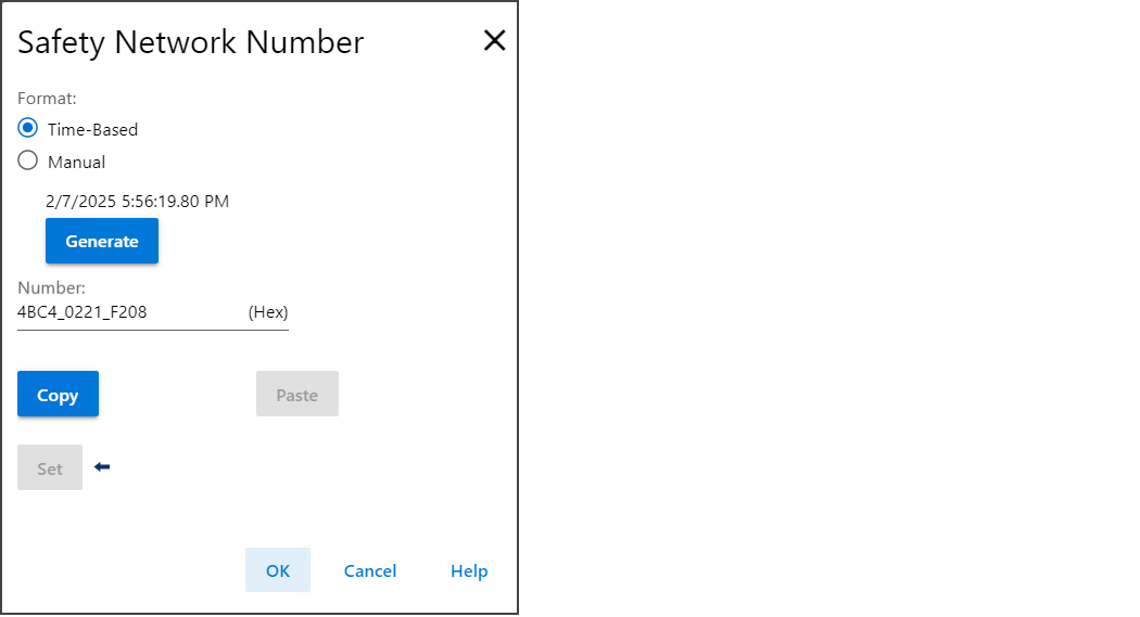
To change the SNN of a device, select the ellipses next to the SNN field in the
General view.
Safety Network Number Example
Provide Feedback